Patient-Specific Drill Guide Template for Pedicle Screw Insertion into the Atlantoaxial Cervical Spine Using Stereolithographic Modeling: An In Vitro Study
- PMID: 36163679
- PMCID: PMC9977983
- DOI: 10.31616/asj.2021.0362
Patient-Specific Drill Guide Template for Pedicle Screw Insertion into the Atlantoaxial Cervical Spine Using Stereolithographic Modeling: An In Vitro Study
Abstract
Study design: Cadaveric study.
Purpose: This study aimed to assess the accuracy and feasibility of cervical pedicle screw (CPS) insertion into the atlantoaxial cervical spine using a patient-specific drill guide template constructed from a stereolithographic model.
Overview of literature: CPS fixation is a widely accepted procedure for posterior cervical fixation because of its biomechanical advantages, particularly in the subaxial cervical region. The extremely narrow corridors of the atlantoaxial spine make CPS insertion more difficult, requiring the development of new tools to ensure accurate placement.
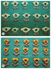
Methods: Fifteen atlantoaxial cervical vertebra specimens from 15 cadavers were scanned into thin slices using computed tomography. Images of the cadaver spine were digitally processed and rendered stl files so that they could be printed to scale as threedimensional (3D) plastic models. Manually molded dental acrylic drill guide templates with pins inserted in the pedicles of the plastic cervical models were placed over the 3D printed models. The drill guide templates were used for precise placement of the drill holes in the pedicles of cadaveric specimens for pedicle screw fixation. The accuracy of screw placement was evaluated by an independent evaluator.
Results: A total of 60 pedicles (combined C1 and C2) from 15 cadaveric axial cervical vertebrae were evaluated. The total acceptable accuracy for pedicle screw insertion in the atlantoaxial cervical vertebrae is 95%. An accuracy rate of 100% was achieved for C1 while an acceptable accuracy rate of 90% was achieved for C2.
Conclusions: The use of a patient-specific drill guide constructed using stereolithography improved the accuracy of CPS placement in a cadaveric model.
Keywords: Axial cervical spine; Cervical pedicle screw fixation; Patient-specific surgical template; Stereolithography; Three-dimensional printing.
Conflict of interest statement
No potential conflict of interest relevant to this article was reported.
Figures


Similar articles
-
A Novel Patient-Specific Drill Guide Template for Pedicle Screw Insertion into the Subaxial Cervical Spine Utilizing Stereolithographic Modelling: An In Vitro Study.Asian Spine J. 2017 Feb;11(1):4-14. doi: 10.4184/asj.2017.11.1.4. Epub 2017 Feb 17. Asian Spine J. 2017. PMID: 28243363 Free PMC article.
-
[Design and experimental study of individual drill templates for atlantoaxial pedicle screw fixation].Zhongguo Xiu Fu Chong Jian Wai Ke Za Zhi. 2010 Oct;24(10):1168-73. Zhongguo Xiu Fu Chong Jian Wai Ke Za Zhi. 2010. PMID: 21046800 Chinese.
-
Accuracy assessment of atlantoaxial pedicle screws assisted by a novel drill guide template.Arch Orthop Trauma Surg. 2016 Nov;136(11):1483-1490. doi: 10.1007/s00402-016-2530-9. Epub 2016 Aug 16. Arch Orthop Trauma Surg. 2016. PMID: 27531494
-
Accuracy and safety assessment of subaxial cervical pedicle screw instrumentation: a systematic review.Spine J. 2025 May 5:S1529-9430(25)00237-2. doi: 10.1016/j.spinee.2025.05.006. Online ahead of print. Spine J. 2025. PMID: 40334991 Review.
-
Pedicle screw placement in spinal neurosurgery using a 3D-printed drill guide template: a systematic review and meta-analysis.J Orthop Surg Res. 2020 Jan 3;15(1):1. doi: 10.1186/s13018-019-1510-5. J Orthop Surg Res. 2020. PMID: 31900192 Free PMC article.
Cited by
-
Design, fabrication, and evaluation of single- and multi-level 3D-printed non-covering cervical spinal fusion surgery templates.Front Bioeng Biotechnol. 2024 Jul 12;12:1416872. doi: 10.3389/fbioe.2024.1416872. eCollection 2024. Front Bioeng Biotechnol. 2024. PMID: 39070162 Free PMC article.
-
3D-printed drill guide versus fluoroscopic-guided free-hand technique for pedicle screw insertion in the upper cervical spine: a systematic review and meta-analysis.Musculoskelet Surg. 2025 Jan 12. doi: 10.1007/s12306-024-00879-1. Online ahead of print. Musculoskelet Surg. 2025. PMID: 39800800 Review.
-
Assessment of Biomechanical Advantages in Combined Anterior-Posterior Cervical Spine Surgery by Radiological Outcomes: Pedicle Screws over Lateral Mass Screws.J Clin Med. 2023 Apr 29;12(9):3201. doi: 10.3390/jcm12093201. J Clin Med. 2023. PMID: 37176646 Free PMC article.
References
-
- John PS. Pedicle screw placement-current concepts. J Orthop. 2004;1:e5.
-
- Ludwig SC, Kramer DL, Vaccaro AR, Albert TJ. Transpedicle screw fixation of the cervical spine. Clin Orthop Relat Res. 1999;(359):77–88. - PubMed
-
- Bransford RJ, Lee MJ, Reis A. Posterior fixation of the upper cervical spine: contemporary techniques. J Am Acad Orthop Surg. 2011;19:63–71. - PubMed
-
- Jackson RS, Banit DM, Rhyne AL, 3rd, Darden BV., 2nd Upper cervical spine injuries. J Am Acad Orthop Surg. 2002;10:271–80. - PubMed
-
- Karaikovic EE, Kunakornsawat S, Daubs MD, Madsen TW, Gaines RW., Jr Surgical anatomy of the cervical pedicles: landmarks for posterior cervical pedicle entrance localization. J Spinal Disord. 2000;13:63–72. - PubMed
Grants and funding
LinkOut - more resources
Full Text Sources
Research Materials
Miscellaneous

