Review
. 2022 Nov;9(31):e2203856.
doi: 10.1002/advs.202203856. Epub 2022 Oct 3.

Smart Electronic Textile-Based Wearable Supercapacitors

Affiliations
Review

Smart Electronic Textile-Based Wearable Supercapacitors

Md Rashedul Islam et al. Adv Sci (Weinh). 2022 Nov.

Abstract

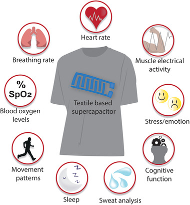
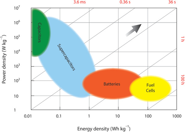
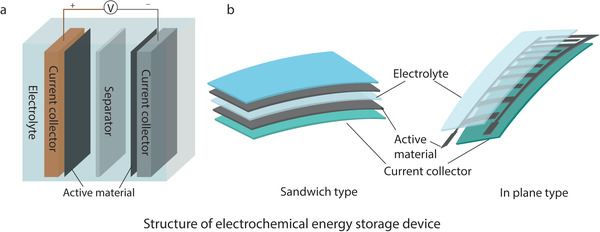
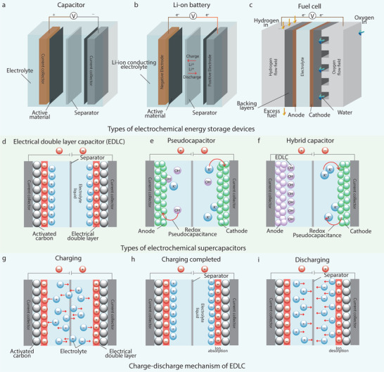
Electronic textiles (e-textiles) have drawn significant attention from the scientific and engineering community as lightweight and comfortable next-generation wearable devices due to their ability to interface with the human body, and continuously monitor, collect, and communicate various physiological parameters. However, one of the major challenges for the commercialization and further growth of e-textiles is the lack of compatible power supply units. Thin and flexible supercapacitors (SCs), among various energy storage systems, are gaining consideration due to their salient features including excellent lifetime, lightweight, and high-power density. Textile-based SCs are thus an exciting energy storage solution to power smart gadgets integrated into clothing. Here, materials, fabrications, and characterization strategies for textile-based SCs are reviewed. The recent progress of textile-based SCs is then summarized in terms of their electrochemical performances, followed by the discussion on key parameters for their wearable electronics applications, including washability, flexibility, and scalability. Finally, the perspectives on their research and technological prospects to facilitate an essential step towards moving from laboratory-based flexible and wearable SCs to industrial-scale mass production are presented.

Keywords: electronic textiles; energy storage devices; smart textiles; supercapacitors; wearable electronics.


Conflict of interest statement

The authors declare no conflict of interest.

Figures

Figure 1
Figure 1
Textile‐based flexible supercapacitors for powering up wearable devices to monitor physiological parameters.
Figure 2
Figure 2
Ragone plot showing comparison of different electrochemical energy storage systems.
Figure 3
Figure 3
Schematic diagram of the structure of electrochemical energy storage devices. a) Conventional rigid form and b) flexible form.
Figure 4
Figure 4
Basic schematic of electrochemical energy storage devices: a) a capacitor, b) a Li‐ion battery, and c) a fuel cell. Types of electrochemical supercapacitors: d) EDLC, e) Pseudocapacitor, f) Hybrid capacitor, and g–i) Charge‐discharge mechanism of an EDLC.
Figure 5
Figure 5
Typical a) CV curves and c) galvanostatic charge‐discharge (GCD) curves for ideal supercapacitor; b) CV curve and d) GCD curve distortion due to faradaic reactions.[ 55 ]
Figure 6
Figure 6
Approaches for enhancing energy and power densities of supercapacitor.[ 64 ]
Figure 7
Figure 7
Electrode materials for textile‐based supercapacitors: a) carbonaceous materials, b) conductive polymers, c) metal oxides/hydroxides, and d) other 2D materials.
Figure 8
Figure 8
Comparison of the performance of several electrolyte types.
Figure 9
Figure 9
a) Schematic diagram of dip coating technique. b) Conductive textiles fabricated by dipping textile into an aqueous SWNT ink followed by drying in oven at 120 °C for 10 min. c) SEM image of coated cotton reveals the macroporous structure of the cotton sheet coated with SWNTs on the cotton fiber surface. d) Ragone plot of commercial SCs, SWNT SC on metal substrates, and SWNT SC on porous conductors including all the weight. Reproduced with permission.[ 223 ] Copyright 2010, American Chemical Society. e) Photograph of a stable, solution‐exfoliated graphene ink suspension prepared by ultrasonication of the graphite powder in a water sodium cholate solution, and a 6 cm X 8 cm graphene‐coated conductive textile sheet (polyester fabrics). f) SEM image of a sheet of graphene‐coated textile after 60 min MnO2 electrodeposition showing large‐scale, uniform deposition of MnO2 nanomaterials achieved on almost entire fabric fiber surfaces, Scale bar: 200 µm. Reproduced with permission.[ 224 ] Copyright 2011, American Chemical Society. g) The change in resistance with the number of washing cycles of G‐coated compressed (with encapsulation) poly‐cotton fabric, G‐coated only (with encapsulation) poly‐cotton fabric, and G‐coated compressed (without encapsulation) poly‐cotton fabric. h) Cyclic voltammograms (CV) recorded for the supercapacitor device at different scan rates i) CV curves for the ASC device at different bending angles. Reproduced with permission.[ 225 ] Copyright 2020, Wiley‐VCH.
Figure 10
Figure 10
SEM pictures of a) shieldex conductive yarn wrapped with PP staple fiber, b) Melt coated single yarn, and c) Melt coated plied yarn. Reproduced with permission.[ 228 ] Copyright 2012, Taylor & Francis. d) Schematic illustration of the structure of the electrochromic, wearable fiber‐shaped supercapacitor. e) Positive electrode demonstrates rapid and reversible chromatic transitions between blue, green, and light yellow under different working states. f) An energy storage textile woven from electrochromic fiber‐shaped supercapacitors during the charge–discharge process. g,h) Electrochromic fiber‐shaped supercapacitors that have been designed and woven to display the signs “+” and “F”, respectively. i) Cyclic voltammograms at various scan rates. j) Galvanostatic charge–discharge profiles at different current densities. Reproduced with permission.[ 229 ] Copyright 2014, Wiley‐VCH. k) Photographs of an SFSC transformed into different shapes and sizes. l,m) Galvanostatic charging and discharging curves of SFSCs arranged in series and parallel, respectively. The galvanostatic charging and discharging tests were performed at a current density of 0.5 A g−1. n) Photographs of the same smart clothes woven from SFSCs that were “frozen” into different shapes and sizes. Reproduced with permission.[ 230 ] Copyright 2015, Wiley‐VCH.
Figure 11
Figure 11
a) Schematic representation of the printed in‐plane supercapacitor fabrication process. Electrochemical characterization of printed graphene on textile. b) CV at different scan rates and c) charge/discharge curves at different current densities. Reproduced with Permission.[ 239 ] Copyright 2017, IOP Publishing Ltd. d) Images of all printed solid‐state flexible SC devices on PET, paper, and textile substrates, e) images of these SCs after bending, f) image of these SCs in series lighting up a yellow LED, and g) images of the same after bending these SCs. Reproduced with permission.[ 240 ] Copyright 2017, Elsevier B.V.
Figure 12
Figure 12
a) Schematic drawing of the inkjet process and ink spreading behavior on the film and textile substrates. Reproduced with permission.[ 244 ] Copyright 2021, American Chemical Society. b) Detailed steps of fabrication of inkjet‐printed textile supercapacitor and printed samples. Reproduced with permission.[ 254 ] Copyright 2021, The Authors. c) CV curves of MnO2–NiCo2O4//rGO asymmetric device at different scan rates. d) GCD profiles of the MnO2–NiCo2O4//rGO asymmetric device at various current densities and e) Capacitance retention of the device with the different number of charge–discharge cycles. Reproduced with permission.[ 255 ] Copyright 2020, The Authors.
Figure 13
Figure 13
a) Schematic illustration showing the coaxial spinning process. Two‐ply YSCs and their electrochemical properties. b) SEM images of cross‐sectional view of a two‐ply YSC. The arrow area is PVA/H3PO4 electrolyte (scale bar: 50 µm) c) CV curves of RGO+CNT@CMC. d) GCD curves of RGO+CNT@CMC. Reproduced with permission.[ 264 ] Copyright 2014, The Authors. e) Schematic illustration of the textile based SC fabrication process. The inset shows details of one‐step electrospinning setup. f) Photographs of the pristine cotton fabric, Ni‐coated cotton fabric (Ni–cotton), and CNF web‐coated Ni–cotton fabric (C‐web@Ni–cotton). g) Photographs of a large supercapacitor fabric (active area: 4 cm× 4 cm) enclosed with commercial nonconductive fabrics. h) CV curves of solid‐state C‐web@Ni–cotton supercapacitor fabric. i) Summary of the areal capacitance of the supercapacitor at different current densities. Reproduced with permission.[ 267 ] Copyright 2016, The Royal Society of Chemistry.
Figure 14
Figure 14
a) Design and manufacturing process flow of magnetic‐assisted self‐healable supercapacitor. Fe3O4 nanoparticles anchor on the surface of yarn by a microwave‐assisted hydrothermal method. The processed yarn is annealed to ensure the magnetic particles anchor on the yarn tightly. To achieve a better electrochemical performance, a layer of PPy is electrodeposited on the annealed yarn. Finally, two yarns as a set of electrodes are assembled with a solid electrolyte and a self‐healing shell to form a self‐healing supercapacitor. b) Schematic illustration of supercapacitor's self‐healing process. The magnetic alignment could assist the reconnection of fibers in broken yarn electrodes when they are brought together, as shown in inset image. c) From top to bottom, pristine yarn, hydrothermal and annealing‐treated yarn, and PPy‐electrodeposited yarn. Electrochemical measurements for as‐prepared capacitor. d) CVs obtained at various scan rates. e) CVs after healing for different cycles. f) Specific capacitance of the original device and after healing for different cycles. Reproduced with permission.[ 299 ] Copyright 2015, American Chemical Society. g) Fabrication process and characterization of carbonized plain weave cotton fabric (CPCF)‐ Photograph of a pristine cotton fabric h) Photograph of the CPCF made from (g). i) A flexible CPCF‐based strain sensor. j,k) SEM image and TEM image of the CPCF. Reproduced with permission.[ 306 ] Copyright 2016, Wiley‐VCH.
Figure 15
Figure 15
Textile‐based energy storage device configuration. 1D substrate forms a) filament fibers, b) staple fibers, c) two plied, d) multiplied, e) split film, and f) core‐sheath yarn, g) multifilament, h) monofilament, and i) staple yarn. 2D substrate forms j) knitted, k) non‐woven, l) woven, and m) braided fabric. Textile supercapacitor forms n) 1D fiber or yarn shaped o) Sandwich type and p) in plane type 2D supercapacitor.
Figure 16
Figure 16
Fabrication of textile‐based supercapacitor devices. 1D shaped textiles, a) fiber, b) filament, c) yarn, and 2D shaped fabric and c) conductive materials. Preparation of conductive textiles by f) spinning, g) printing, h) coating, and i) in situ growth of active sites on textiles to produce. j) 1D shaped energy storage textiles, 2D shaped k) sandwich type and l) in‐plane type supercapacitor, and m) the final e‐textiles.
Figure 17
Figure 17
a,b) Demonstration of the hybrid SC–BFC device, Photographs showing the application of three SCs charged by five BFCs to light LEDs using the following procedure: c) without lactate, no power; d) with lactate, LEDs were turned on; e) upon disconnecting BFCs and SCs, LEDs could still be turned on. f) The integrated chemical self‐powered system on one piece of textile was applied to the arm of a volunteer. The SC and BFC were printed outside and inside the textile band, respectively. g) The real‐time voltage of the printed SC charged from the on‐body BFC during a constant cycling exercise for 56 min. The SC charged by lactate BFC immobilized with LOx (blue plot) and without LOx as a control (black plot). Reproduced with permission.[ 331 ] Copyright 2018, The Royal Society of Chemistry. h) Assembled textile power module and i) FEP‐textile ferroelectret charging the 2 mF textile capacitor. Reproduced with permission.[ 332 ] Copyright 2019, Wiley‐VCH.
Figure 18
Figure 18
Flexibility tests of PPy@MnO2@rGO‐deposited conductive yarns measured in the two‐electrode cell. a) CV curves of the all‐solid‐state yarn supercapacitor undergoing consecutive deformations at a scan rate of 100 mV s−1.b) GCD curves of the all‐solid‐state yarn supercapacitor undergoing consecutive deformations at a current density of 80 mA cm−3. c) Capacitance ratio under various deformations. d) Capacitance retention of the all‐solid‐state yarn supercapacitor after each deformation. Reproduced with permission.[ 418 ] Copyright 2015, American Chemical Society. Influence of bending deformation on CeO2‐ACVF capacitive performance; specific capacitance e) under various bending angles; and f) after different bending cycles. ACVF: activated viscose fabric. Reproduced with permission.[ 396 ] Copyright 2020, SAGE Publications.
Figure 19
Figure 19
a) Schematic diagram of washing test. Reproduced with permission.[ 486 ] Copyright 2019, The Royal Society of Chemistry. b) Illustration of graphene‐based ink pattern and encapsulation layer on textile substrate. c) The change in electrical resistance with number of washing cycles of graphene‐based ink printed (without encapsulation) and graphene‐based ink‐printed (with encapsulation) cotton fabric. Reproduced with permission.[ 358 ] Copyright 2022, Elsevier. d) Resistances of electrode after being immersed in water for different times. The inset is the photograph of electrode immersed in water for 1 week (scale bar:, 20 mm). e) Resistances of same electrode on nylon substrate after being immersed in water for different times and 2 h for each time. Reproduced with permission.[ 487 ] Copyright 2018, American Chemical Society.
Figure 20
Figure 20
Future research direction of flexible supercapacitors.

Similar articles

Cited by

References

    1. Wicaksono I., Tucker C. I., Sun T., Guerrero C. A., Liu C., Woo W. M., Pence E. J., Dagdeviren C., npj Flexible Electron. 2020, 4, 5. - PMC - PubMed
    1. Ismar E., Kurşun Bahadir S., Kalaoglu F., Koncar V., Global Challenges 2020, 4, 1900092. - PMC - PubMed
    1. Peng H., Sun X., Cai F., Chen X., Zhu Y., Liao G., Chen D., Li Q., Lu Y., Zhu Y., Jia Q., Nat. Nanotechnol. 2009, 4, 738. - PubMed
    1. Shi X., Zuo Y., Zhai P., Shen J., Yang Y., Gao Z., Liao M., Wu J., Wang J., Xu X., Tong Q., Zhang B., Wang B., Sun X., Zhang L., Pei Q., Jin D., Chen P., Peng H., Nature 2021, 591, 240. - PubMed
    1. Wang L., Xie S., Wang Z., Liu F., Yang Y., Tang C., Wu X., Liu P., Li Y., Saiyin H., Zheng S., Sun X., Xu F., Yu H., Peng H., Nat. Biomed. Eng. 2020, 4, 159. - PubMed

Publication types

LinkOut - more resources