Review
. 2023 Jan;44(1-2):268-297.
doi: 10.1002/elps.202200162. Epub 2022 Oct 25.

Recent advances and challenges in temperature monitoring and control in microfluidic devices

Affiliations
Review

Recent advances and challenges in temperature monitoring and control in microfluidic devices

Alejandro A Dos-Reis-Delgado et al. Electrophoresis. 2023 Jan.

Abstract

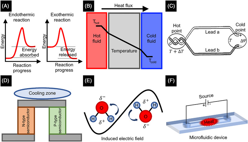
Temperature is a critical-yet sometimes overlooked-parameter in microfluidics. Microfluidic devices can experience heating inside their channels during operation due to underlying physicochemical phenomena occurring therein. Such heating, whether required or not, must be monitored to ensure adequate device operation. Therefore, different techniques have been developed to measure and control temperature in microfluidic devices. In this contribution, the operating principles and applications of these techniques are reviewed. Temperature-monitoring instruments revised herein include thermocouples, thermistors, and custom-built temperature sensors. Of these, thermocouples exhibit the widest operating range; thermistors feature the highest accuracy; and custom-built temperature sensors demonstrate the best transduction. On the other hand, temperature control methods can be classified as external- or integrated-methods. Within the external methods, microheaters are shown to be the most adequate when working with biological samples, whereas Peltier elements are most useful in applications that require the development of temperature gradients. In contrast, integrated methods are based on chemical and physical properties, structural arrangements, which are characterized by their low fabrication cost and a wide range of applications. The potential integration of these platforms with the Internet of Things technology is discussed as a potential new trend in the field.

Keywords: heating; lab-on-a-chip; microfluidics; sensors; temperature.


Conflict of interest statement

The authors have declared no conflict of interest.

Figures

FIGURE 1
FIGURE 1
Mechanisms involved in temperature monitoring and control in microfluidic devices. (A) Graphic representation of the energy released/absorbed during an exothermic/endothermic reaction. (B) Schematic representation of a linear temperature gradient across a microfluidic system. The microfluidic channel between a hot source on the left and a cold sink on the right. Heat flux informs about the direction of the heat flow. The temperature line varies linearly between the hot fluid and the cold one. (C) Schematic representation of the Seebeck effect. An increment of temperature at the hot point where lead a and lead b are connected creates a voltage at the right side where the cables are not connected and at room temperature. (D) Schematic representation of the Peltier effect. p‐Type and n‐type semiconductors are connected at the top by a conductor material, at the bottom, each semiconductor is connected to another conductor material, and a voltage is applied between the two conducting terminals, developing a cooling zone at the top. (E) Schematic representation of microwave heating by the rotation of water molecules induced by the electromagnetic microwave. (F) Schematic representation of Joule heating in an insulator‐based microfluidic system, where heat is mainly generated at regions of high electric field intensity. Source: (C) Reprinted with permission from Ref. [80], © (1986) Elsevier
FIGURE 2
FIGURE 2
(A) Schematic representation of an experimental setup consisting of a microfluidic structure with embedded Tygon tubes for convective heating/cooling of the sample, a syringe pump for infusing the sample through the microfluidic channel, a syringe pump for pulling hot/cold water through the Tygon tubes, a water flask for storing the hot/cold water, a bottle for collection of the waste sample, and an infrared camera interfaced with an analysis software for real‐time monitoring of temperature across the glass coverslip. (B) The image of the microfluidic channel integrated with Pt thermo‐sensor. (C) Illustration of an optical‐based temperature monitoring approach implemented in a microfluidic device. The channel extends to ensure a fully developed flow profile. Black arrows depict the flow direction, red spheres depict dye containing droplets. (D) Overview of a spectroscopy setup used in microfluidic applications. An optical fiber probe excited nanoparticles (NPs) within the microfluidic device using a 980 nm laser coupled into the fiber using a collimator. The light is focused using a lens and is collected with the sample fiber probe. The collected light is monitored with a charge‐coupled device (CCD) detector after passing through a short pass filter. Source: (A) Reprinted with permission from Ref. [68], © (2018) American Chemical Society; (B) reprinted with permission from Ref. [66], © (2021) Elsevier; (C) reprinted with permission from Ref. [25], © (2022) Elsevier; and (D) reprinted with permission from Ref. [128], © (2019) Royal Society of Chemistry
FIGURE 3
FIGURE 3
(A) A schematic of a polymerase chain reaction (PCR) chip fabricated in SU‐8 on a glass substrate. A thin‐film platinum microheater and a thermometer are placed under the SU‐8‐based PCR chamber. (B) Peltier elements placed under a reactor. Schematics of a microreactor with a thermal control composed of a 61‐W Peltier cells and a thermal block. (C) A schematic of a passive heating system for microfluidic devices composed of three microfluidic chambers composed of supercooled sodium acetate trihydrate (SAT) as a heat source placed at the bottom of an organic phase change material (PCM) for thermal regulation and a reagent chamber over the PCM. Source: (A) Reprinted with permission from Ref. [135], © (2004) Elsevier; (B) reprinted with permission from Ref. [72], © (2019) Elsevier; and (C) reprinted with permission from Ref. [73], © (2020) Elsevier
FIGURE 4
FIGURE 4
(A) A schematic of the arrangement of a microfluidic device, in which its sample channel temperature is controlled by the endothermic and exothermic reaction driven by the mixture of two reagents. (B) Heat distribution along a Tygon tubes temperature controlled microfluidic device. (C) A schematic of the fundamental elements of a microwave heater. (D) Configuration of a solenoid embedded microheater in a microchannel. Source: (A) Reprinted with permission from Ref. [147], © (2021) Elsevier; (B) reprinted with permission from Ref. [68], © (2018) American Chemical Society; (C) reprinted with permission from Ref. [148], © (2013) Royal Society of Chemistry; and (D) reprinted with permission from Ref. [69], © (2017) IEEE

References

    1. Peng J, Fang C, Ren S, Pan J, Jia Y, Shu Z, et al. Development of a microfluidic device with precise on‐chip temperature control by integrated cooling and heating components for single cell‐based analysis. Int J Heat Mass Transfer. 2019;130:660–7.
    1. Tsuji T, Matsumoto Y, Kugimiya R, Doi K, Kawano S. Separation of nano‐ and microparticle flows using thermophoresis in branched microfluidic channels. Micromachines. 2019;10:321. 10.3390/mi10050321 - DOI - PMC - PubMed
    1. Liao S‐C, Peng J, Mauk MG, Awasthi S, Song J, Friedman H, et al. Smart cup: a minimally‐instrumented, smartphone‐based point‐of‐care molecular diagnostic device. Sens Actuators B. 2016;229:232–8. - PMC - PubMed
    1. Markovic T, Bao J, Ocket I, Kil D, Brancato L, Puers R, et al. Uniplanar microwave heater for digital microfluidics. In: 2017 first IEEE MTT‐S International Microwave Bio Conference (IMBIOC). 2017. p. 1–4.
    1. Redmond WB, Bowman BU. Studies on autolysis of mycobacteria, the effect of temperature change. J Bacteriol. 1955;69:293–7. - PMC - PubMed

Publication types

LinkOut - more resources