. 2022 Oct 8;19(1):109.
doi: 10.1186/s12984-022-01088-2.

A unilateral robotic knee exoskeleton to assess the role of natural gait assistance in hemiparetic patients

Affiliations

A unilateral robotic knee exoskeleton to assess the role of natural gait assistance in hemiparetic patients

Julio Salvador Lora-Millan et al. J Neuroeng Rehabil. .

Abstract

Background: Hemiparetic gait is characterized by strong asymmetries that can severely affect the quality of life of stroke survivors. This type of asymmetry is due to motor deficits in the paretic leg and the resulting compensations in the nonparetic limb. In this study, we aimed to evaluate the effect of actively promoting gait symmetry in hemiparetic patients by assessing the behavior of both paretic and nonparetic lower limbs. This paper introduces the design and validation of the REFLEX prototype, a unilateral active knee-ankle-foot orthosis designed and developed to naturally assist the paretic limbs of hemiparetic patients during gait.

Methods: REFLEX uses an adaptive frequency oscillator to estimate the continuous gait phase of the nonparetic limb. Based on this estimation, the device synchronically assists the paretic leg following two different control strategies: (1) replicating the movement of the nonparetic leg or (2) inducing a healthy gait pattern for the paretic leg. Technical validation of the system was implemented on three healthy subjects, while the effect of the generated assistance was assessed in three stroke patients. The effects of this assistance were evaluated in terms of interlimb symmetry with respect to spatiotemporal gait parameters such as step length or time, as well as the similarity between the joint's motion in both legs.

Results: Preliminary results proved the feasibility of the REFLEX prototype to assist gait by reinforcing symmetry. They also pointed out that the assistance of the paretic leg resulted in a decrease in the compensatory strategies developed by the nonparetic limb to achieve a functional gait. Notably, better results were attained when the assistance was provided according to a standard healthy pattern, which initially might suppose a lower symmetry but enabled a healthier evolution of the motion of the nonparetic limb.

Conclusions: This work presents the preliminary validation of the REFLEX prototype, a unilateral knee exoskeleton for gait assistance in hemiparetic patients. The experimental results indicate that assisting the paretic leg of a hemiparetic patient based on the movement of their nonparetic leg is a valuable strategy for reducing the compensatory mechanisms developed by the nonparetic limb.

Keywords: Gait symmetry; Hemiparetic gait; Robotic exoskeleton; Stroke patients; Unilateral assistance.


Conflict of interest statement

The authors declare that they have no competing interests.

Figures

Fig. 1
Fig. 1
REFLEX prototype for the assistance of the knee joint of the paretic leg. This joint is actuated by a DC motor coupled to a Harmonic Drive while the ankle remains unactuated. The sensors of the prototype are a potentiometer to measure the exoskeleton flexion in the sagittal plane, strain gauges to measure the interaction torque, inertial sensors (IMUs) to acquire the lower-limbs kinematics, and insole pressure sensors to detect floor contact events
Fig. 2
Fig. 2
Control paradigm. A Examples of healthy and hemiparetic gait patterns. B An overview of the control algorithm. The assistance provided by the robotic exoskeleton is synchronized with the movement of the unassisted leg. The unassisted hip angle feeds an adaptive frequency oscillator to estimate the unassisted leg’s gait phase in realtime. This phase is shifted 180° to obtain the gait phase for the assisted leg. The gait phase of both legs and the unassisted knee movement are used to generate the pattern to be followed by the exoskeleton through the low-level controller to assist the movement of the assisted limb
Fig. 3
Fig. 3
Pattern generation according to the Echo-control assistive strategy based on replicating the kinematics of the unassisted leg. The knee movement during a step is stored in a five-step buffer and used to calculate the mean pattern of the unassisted knee; afterward, this averaged movement is provided as the targeted reference for the robotic exoskeleton according to the gait phase estimated for the assisted limb
Fig. 4
Fig. 4
Assistive pattern generation based on synchronizing a healthy gait pattern. The knee pattern is scaled and shifted according to the features extracted from the movement of the unassisted leg; afterward, it is provided as the set point for the robotic exoskeleton according to the gait phase estimated for the assisted limb
Fig. 5
Fig. 5
Low-level controller of REFLEX. A The block diagram of the variable impedance controller; this controller assists the knee movement following the kinematic reference and according to an Assisted-As-Needed paradigm. B The two assistance strategies followed during a single step: the exoskeleton reinforces the joint during the stance phase while it guides the movement during the swing phase; following the Assisted-As-Needed paradigm, the exoskeleton is able to provide different assistance levels by using different force tunnels as depicted in the image
Fig. 6
Fig. 6
Example of AO results during the trial of one healthy subject walking at variable gait velocity. A Compares the AO phase estimation (solid orange line) with the offline phase calculated based on the heel strike detected by the insole pressure sensors (dashed cyan line) during a trial segment. B The median phase estimation during a step in the trial and median error during the step; areas represent the 10th–90th percentiles. C Compares the gait frequency estimated by the AO in real-time (solid orange line) with the gait frequency calculated offline based on heel strikes (dashed cyan line) during the trial. For all the panels, purple lines show the error between the AO estimation and the offline result and are represented with respect to the right axis
Fig. 7
Fig. 7
Example of set point generation with the experimental data of one healthy subject. A An example of the set-point calculated by the two assistive strategies (Pattern in blue and Echo in orange); they are compared with the movement of the master leg that fed the algorithm (brown dashed line) and with the movement of the equivalent leg whose motion should be synchronized with the generated set point (red dashed line). B Compares the phase portrait of the movement of the master leg (in brown) with the set point generated by the Pattern assistive strategy (in blue) or the echo assistive strategy (in orange). Two experimental conditions were evaluated: variable gait speed (two left panels) and constant gait speed (two right panels)
Fig. 8
Fig. 8
Assessment of the set-point generated by the two assistive strategies. A The phase portrait similarity between the set-point and the movement of the master leg used for generating it. B The correlation between the set-point and the movement of the equivalent leg (a correlation of 1 corresponds to a perfect synchronization). Length bars indicate the median value and whiskers indicate the 10th–90th percentiles. C The boxplot of the delays between the maximum knee flexion between the set point and the movement of the equivalent leg. Markers (*) show significant differences between experimental conditions
Fig. 9
Fig. 9
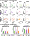
Phase portrait representation of the knee movement from the trials performed by a healthy subject (HS1). Orange lines correspond to the movement of the assisted knee while cyan lines correspond to the movement of the unassisted knee; brown lines correspond to the set point followed by the robot. Solid lines represent the median movement, while semi-transparent lines correspond to the movement of individual steps. When the user wears the robot, the phase portrait of the assisted leg changes in hip and knee joints; however, the action of the robot during Echo and Pattern conditions compensates for the effect of wearing the robot and makes the phase portrait of the assisted leg more closely approach to the portrait of the unassisted leg
Fig. 10
Fig. 10
A The median phase portrait for each leg; Columns 1–4 include information for each experimental condition. Solid lines represent the assisted leg, and dashed lines represent the unassisted leg. B The similarity between the areas of the phase portrait: Panel B1 represents the similarity between both limbs under each experimental condition, and Panels B2 and B3 represent the similarity between the movement under the current experimental condition and the movement during NoExo for each leg. Across the figure, data for the same healthy subject (HS) is represented in the same color (green for HS1, purple for HS2, orange for HS3) while the brightness indicates the experimental condition (from darkest to lightest: NoExo, Free, Echo, and Pattern). Similarity decreases because of wearing the robot; however, the assistance provided by the exoskeleton actively improves similarity in all patients
Fig. 11
Fig. 11
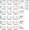
Knee kinematics symmetry for healthy subjects. Rows A and B represent the knee Range of Motion and the phase at maximum flexion for the knee. Columns 1–3 represent the result for each subject; markers indicate the median value and whiskers the 10–90 percentiles. Column 4 represents the symmetry index for each subject under each experimental condition; notice that symmetry indexes closer to 0 mean a higher symmetry between limbs. Across the figure, colors represent the same healthy subject (HS) (HS1 in green, HS2 in purple and HS3 in orange), the brightness represents the experimental condition (from darkest to lightest: No-Exo, Free, Echo and Pattern correspondingly) and the shape of the marker represents the assessed limb (circle for the assisted limb and triangle for the unassisted leg). Markers (*) show significant differences between experimental conditions within a limb of a subject
Fig. 12
Fig. 12
Example of step data from a hemiparetic patient (P2) during the different experimental conditions. Columns 1–4 include information for each experimental condition: NoExo, Free, Echo, and Pattern correspondingly while rows AC show the knee kinematics (A), its phase portrait (B), and the foot contact with the floor (C). Information is represented for both legs: the paretic leg is represented in orange while the unassisted leg is represented in cyan. For the assistive experimental conditions, the exoskeleton set point is also represented in brown
Fig. 13
Fig. 13
Knee flexion phase portraits for three stroke patients. A The median phase portrait for each limb, columns 1–4 include information for each experimental condition, while rows AC show the data for the three patients. Solid lines are used for the impaired leg, while dashed lines are used for the nonparetic leg. B The similarity between phase portraits; Panel B1 represents the similarity between both limbs under each experimental condition, and panels B2B3 represent the similarity between the movement of the current experimental condition and the movement during NoExo. Across the figure, data for the same patient (P) are represented by the same color (green for P1, purple for P2, and orange for P3) while the brightness indicates the experimental condition (from darkest to lightest: NoExo, Free, Echo, and Pattern)
Fig. 14
Fig. 14
Knee kinematics symmetry for stroke patients. Rows A and B represent the knee range of motion and the phase at maximum flexion for the knee. Columns 1–3 represent the result for each subject; the markers indicate the median value, and the whiskers indicate the 10th–90th percentiles. Column 4 represents the symmetry index for each subject under each experimental condition; notice that symmetry indices closer to 0 indicate greater symmetry between limbs. Across the figure, identical colors represent the same patient (P) (P1 in green, P2 in purple and P3 in orange), the brightness represents the experimental condition (from lightest to darkest: No-Exo, Free, Echo and Pattern correspondingly) and the shape of the marker represents the assessed limb (circle for the assisted limb and triangle for the unassisted leg). Markers (*) show significant differences between experimental conditions within a limb of a subject
Fig. 15
Fig. 15
Gait features symmetry for stroke patients. Rows A to F include different gait metrics: step length (A), step time (B), step velocity (C), single-support duration (D), stance phase duration (E), and swing time (F). Columns 1–3 represent the result for each subject; markers indicate the median value and whiskers denote the 10th–90th percentiles. Column 4 represents the symmetry index for each subject under each experimental condition; notice that symmetry indices closer to 0 indicate a higher symmetry between limbs. Across the figure, identical colors represent the same patient (P) (P1 in green, P2 in purple and P3 in orange), the brightness represents the experimental condition (from lightest to darkest: No-Exo, Free, Echo and Pattern correspondingly) and the shape of the marker represents the assessed limb (circle for the assisted limb and triangle for the unassisted leg). Markers (*) show significant differences between experimental conditions within a limb of a subject
Fig. 16
Fig. 16
Examples of the three references generated by the Echo strategy (angle, velocity, and acceleration for rows AC) during trials with a healthy subject (column 1) or a stroke patient (column 2). Red lines represent the content of the five steps buffer, the blue line is the average step, and the green line is the smoothed average step that serves as the pattern reference

Similar articles

Cited by

References

    1. Timmis A, Townsend N, Gale CP, Torbica A, Lettino M, Petersen SE, et al. European society of cardiology: cardiovascular disease statistics 2019. Eur Heart J. 2020;41:12–85. doi: 10.1093/eurheartj/ehz859. - DOI - PubMed
    1. Virani SS, Alonso A, Aparicio HJ, Benjamin EJ, Bittencourt MS, Callaway CW, et al. Heart disease and stroke statistics—2021 update. Circulation. 2021;143:E254–743. doi: 10.1161/CIR.0000000000000950. - DOI - PubMed
    1. Wafa HA, Wolfe CDA, Emmett E, Roth GA, Johnson CO, Wang Y. Burden of stroke in Europe: thirty-year projections of incidence, prevalence, deaths, and disability-adjusted life years. Stroke. 2020;51:2418–2427. doi: 10.1161/STROKEAHA.120.029606. - DOI - PMC - PubMed
    1. Duncan PW, Zorowitz R, Bates B, Choi JY, Glasberg JJ, Graham GD, et al. Management of adult stroke rehabilitation care. Stroke. 2005 doi: 10.1161/01.STR.0000180861.54180.FF. - DOI - PubMed
    1. Langhorne P, Coupar F, Pollock A. Motor recovery after stroke: a systematic review. Lancet Neurol. 2009;8:741–754. doi: 10.1016/S1474-4422(09)70150-4. - DOI - PubMed

Publication types