

Unified risk analysis in radiation therapy
- PMID: 36210227
- PMCID: PMC10751707
- DOI: 10.1016/j.zemedi.2022.08.006
Unified risk analysis in radiation therapy
Abstract
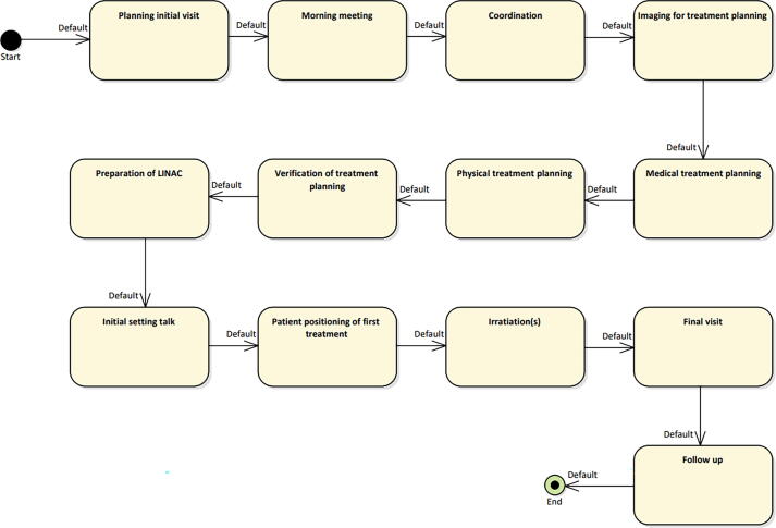
Purpose: The increasing complexity of new treatment methods as well as the Information Technology (IT) infrastructure within radiotherapy require new methods for risk analysis. This work presents a methodology on how to model the treatment process of radiotherapy in different levels. This subdivision makes it possible to perform workflow-specific risk analysis and to assess the impact of IT risks on the overall treatment workflow.
Methods: A Unified Modeling Language (UML) activity diagram is used to model the workflows. The subdivision of the workflows into different levels is done with the help of swim lanes. The model created in this way is exported in an xml-compatible format and stored in a database with the help of a Python program.
Results: Based on an existing risk analysis, the workflows CT Appointment, Glioblastoma Multiforme, and Deep Inspiration Breath Hold (DIBH) were modeled in detail. Part of the analysis are automatically generated workflow-specific risk matrices including risks of medical devices incorporated into a specific workflow. In addition, SQL queries allow to quickly retrieve e.g., the details of the medical device network installed in a department.
Conclusion: Activity diagrams of UML can be used to model workflows in radiotherapy. Through this, a connection between the different levels of the entire workflow can be established and workflow-specific risk analysis is possible.
Keywords: Activity diagram; IEC 80001-1; Risk analysis; UML.
Copyright © 2022. Published by Elsevier GmbH.
Conflict of interest statement
Declaration of Competing Interest The authors declare that they have no known competing financial interests or personal relationships that could have appeared to influence the work reported in this paper.
Figures


Similar articles
-
A uniform and versatile surface-guided radiotherapy procedure and workflow for high-quality breast deep-inspiration breath-hold treatment in a multi-center institution.J Appl Clin Med Phys. 2022 Mar;23(3):e13511. doi: 10.1002/acm2.13511. Epub 2022 Jan 20. J Appl Clin Med Phys. 2022. PMID: 35049108 Free PMC article.
-
Initial end-to-end testing of the ExacTrac dynamic deep inspiration breath hold workflow using a breath hold breast phantom.Phys Eng Sci Med. 2023 Sep;46(3):1239-1247. doi: 10.1007/s13246-023-01291-y. Epub 2023 Jun 22. Phys Eng Sci Med. 2023. PMID: 37349630 Free PMC article.
-
[Modeling the requirements on routine data of general practitioners from the health-care researcher's point of view with the help of unified modeling langauge (UML)].Gesundheitswesen. 2012 Aug;74(8-9):e68-75. doi: 10.1055/s-0032-1314824. Epub 2012 Jul 26. Gesundheitswesen. 2012. PMID: 22836932 German.
-
Does deep inspiration breath-hold prolong life? Individual risk estimates of ischaemic heart disease after breast cancer radiotherapy.Radiother Oncol. 2019 Feb;131:202-207. doi: 10.1016/j.radonc.2018.07.024. Epub 2018 Aug 7. Radiother Oncol. 2019. PMID: 30097250 Clinical Trial.
-
Reducing Cardiac Radiation Dose From Breast Cancer Radiation Therapy With Breath Hold Training and Cognitive Behavioral Therapy.Top Magn Reson Imaging. 2020 Jun;29(3):135-148. doi: 10.1097/RMR.0000000000000241. Top Magn Reson Imaging. 2020. PMID: 32568976 Review.
References
-
- DIN EN 80001-1:2011-11: Anwendung des Risikomanagements für IT-Netzwerke, die Medizinprodukte beinhalten.
-
- Stamatis D.H. second ed. American Society for Quality Press; 2003. Failure Mode and Effect Analysis: Fmea from Theory to Execution.
MeSH terms
LinkOut - more resources
Full Text Sources
