Review
. 2022 Dec;9(34):e2202278.
doi: 10.1002/advs.202202278. Epub 2022 Oct 13.

Emerging Magnetic Fabrication Technologies Provide Controllable Hierarchically-Structured Biomaterials and Stimulus Response for Biomedical Applications

Affiliations
Review

Emerging Magnetic Fabrication Technologies Provide Controllable Hierarchically-Structured Biomaterials and Stimulus Response for Biomedical Applications

Jacek K Wychowaniec et al. Adv Sci (Weinh). 2022 Dec.

Abstract

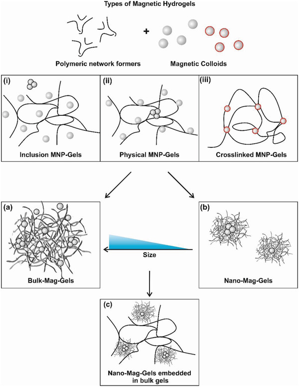
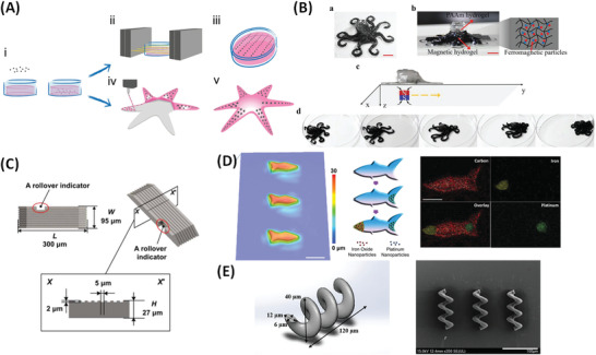
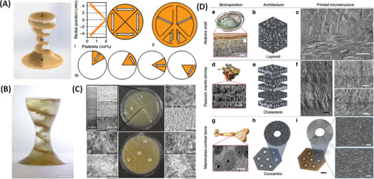
Multifunctional nanocomposites which exhibit well-defined physical properties and encode spatiotemporally-controlled responses are emerging as components for advanced responsive systems. For biomedical applications magnetic nanocomposite materials have attracted significant attention due to their ability to respond to spatially and temporally varying magnetic fields. The current state-of-the-art in development and fabrication of magnetic hydrogels toward biomedical applications is described. There is accelerating progress in the field due to advances in manufacturing capabilities. Three categories can be identified: i) Magnetic hydrogelation, DC magnetic fields are used during solidification/gelation for aligning particles; ii) additive manufacturing of magnetic materials, 3D printing technologies are used to develop spatially-encoded magnetic properties, and more recently; iii) magnetic additive manufacturing, magnetic responses are applied during the printing process to develop increasingly complex structural arrangement that may recapitulate anisotropic tissue structure and function. The magnetic responsiveness of conventionally and additively manufactured magnetic hydrogels are described along with recent advances in soft magnetic robotics, and the categorization is related to final architecture and emergent properties. Future challenges and opportunities, including the anticipated role of combinatorial approaches in developing 4D-responsive functional materials for tackling long-standing problems in biomedicine including production of 3D-specified responsive cell scaffolds are discussed.

Keywords: advanced manufacturing technologies; controlled release; magnetic hydrogels; magnetic hyperthermia; magnetic patterning; soft robotics.


Conflict of interest statement

The authors declare no conflict of interest.

Figures

Figure 1
Figure 1
Scheme depicting the different types of responses obtained from magnetic nanocomposite hydrogels (Mag‐Gels) on exposure to DC‐ (static) or AC‐ (alternating) magnetic fields. These stimuli can be combined to generate targeted therapies, for instance using field‐gradients to guide magnetic nano‐agents that release cargo on AC‐field stimulus.
Figure 2
Figure 2
Schematic classification of different polymer gels incorporating MNPs. i) “Inclusion MNP‐Gels” with chemically cross‐linked networks and entrapped particles; ii) “Physical MNP‐Gels,” as above, with persistent physical interactions between MNPs and network‐forming chains; iii) “Crosslinked MNP‐Gels,” hybrid networks with particles cross‐linking chains by chemical or persistent physical interactions. Representations of; a) “Bulk‐Mag‐Gels,” and b) “Nano‐Mag‐Gels,” which can be formed from any of (i)–(iii). Finally; c) “Bulk‐Nano‐Mag‐Gels” in which Nano‐Mag‐Gels are incorporated in a bulk hydrogel network, these may also be formed by dispersing microscale Mag‐Gels. The formation of MNP clusters during nanocompositing may occur, hence the inclusion of some MNP trimers in (i)–(ii), (a)–(c). Clusters are less common in (iii) as single particles are used as cross‐linking points.
Figure 3
Figure 3
A) Schematic representation of commonly used magnet types with simulated of field lines for a neodymium alloy magnet a Halbach array and a Helmholz coil. B) Actuation systems consisting of two neodymium magnets attached to a moveable robotic arm. Reproduced with permission.[ 34 ] Copyright 2018, Elsevier. C) Proof of principle arrangement of 16 (Halbach) paired permanent magnets (grey, producing a strong uniform dipolar field) surrounded by 8 magnets (green, producing a graded quadrupolar field), which can be rotated relative to each other, generating accessible uniform (several kilogauss) or dipolar fields, the B x and B y components of the flux are shown. Reproduced with permission.[ 35 ] Copyright 2017, Elsevier. D) Schematic diagram of a fluidic chip inserted into a magnetic mixing system with easily exchangeable magnetic heads. Possible magnetic flux distributions of the magnet combinations are shown. Reproduced with permission.[ 36 ] Copyright 2019, The Royal Society of Chemistry.
Figure 4
Figure 4
Magnetic hydrogelation. Schematic representations of hydrogelation process of magnetic colloids embedded in polymeric matrices. A) Hydrogelation can occur in the absence of a static‐field. B) Static‐field stimulus can be applied to induce alignment of magnetic colloids within the network, subsequent hydrogelation occurs over time and/or following an intervention, for example, enzymatically, UV crosslinking, or by temperature induced setting. C) Processing steps and torques involved during the magnetically assisted slip casting (MASC) process. Rotating magnetic fields were applied using a 300 mT neodymium magnet mounted on an electrical motor. Reproduced with permission.[ 46 ] Copyright 2019, The Royal Society of Chemistry. D) Processing of gelatin‐based composites with magnetic control over the orientation or distribution of the m‐rGO flakes. Magnetic assembly is performed in the liquid phase with subsequent matrix consolidation to yield composites with tailored structures at both nano‐ and microscales. The wells were positioned on a neodymium magnet (250 mT). Reproduced under the terms of a Creative Commons Attribution 4.0 International License.[ 42 ] Copyright 2016, The Authors, published by Springer Nature.
Figure 5
Figure 5
Bottom‐up approach with layer‐by‐layer deposition of a bio‐ink to produce 3D scaffolds, including gelation (e.g., light, ionic, pH, temperature, host–guest interaction, enzymatic) between depositions of single layers. Reproduced with permission.[ 50 ] Copyright 2020, American Chemical Society.
Figure 6
Figure 6
A) Magnetic inkjet printing. a) Schematic of an inkjet printing and magnetic alignment setup. b) Photos and schematics of an x‐aligned square, and a radially‐aligned ring sample. Reproduced with permission.[ 54 ] Copyright 2014, AIP Publishing LLC. B) Magnetic layer by layer deposition. Schematic of step‐by‐step device fabrication within a PDMS chamber. Reproduced with permission.[ 55 ] Copyright 2018, MyJoVE Corporation. C) Magnetic extrusion‐based printing. Schematics of the MM‐3D platform for printing heterogeneous composites. a) Direct ink‐writing hardware equipped with multiple I) dispensers, II) mixing unit, III) movable head and table, IV) magnet, and V) a curing unit. b) Example of a print designed to change shape on stimulus by incorporation of inks of different stiffness and swelling. c–e) Illustrations of typical ink constituents. c) Oligomers and monomers that form the base material and are crosslinked after deposition to generate a polymer network. d) Fumed silica (FS) nanoparticles that percolate throughout the resin. e) Anisotropic particles oriented by the external magnetic field. f) Chemical structures of typical ink monomers/oligomers. g) SEM image of FS particles. Scale bar, 500 nm. h) SEM image of alumina platelets. Scale bar, 10 mm. Reproduced under the terms of a Creative Commons Attribution 4.0 International License.[ 56 ] Copyright 2015, The Authors, published by Springer Nature. D) Magnetic stereolithography. a) This 3D system uses DLP to UV‐photopolymerise in a movable static‐field generated using solenoids, which, b) aligns and selectively polymerizes groupings of voxels programmed to have specific reinforcement orientation within each layer. The build plate peels after a layer is complete to print additional layers. c) Example of a reinforced micro‐architecture (a gold rectangle with feature sizes ≤90 mm. Scale bars 2, 500, and 50 mm (left to right). Reproduced under the terms of a Creative Commons Attribution 4.0 International License.[ 57 ] Copyright 2015, The Authors, published by Springer Nature.
Figure 7
Figure 7
A) Scheme showing typical strategies for AC‐field induced Mag‐Gel therapeutic delivery, including; i) temperature‐induced increase in molecular diffusion, and deswelling of; ii) Bulk‐Mag‐Gels, or; iii) Nano‐Mag‐Gels composed of thermoresponsive components, and; iv) inclusion of thermoresponsive Nano‐Mag‐Gels in non‐response bulk matrices. B) Vitamin B12 release from Bulk‐Mag‐Gels on application of pulsed AC‐field (pulses are labelled “F”), % represents vitamin B12 loading by weight in pNIPAM–TEGDMA (Triethylene glycol dimethacrylate) nanocomposite. C) Methylene blue release under the same conditions. Reproduced with permission.[ 66 ] Copyright 2008, Elsevier. D) Release kinetics of doxorubicin from pNIPAM‐co‐Am Nano‐Mag‐Gels was observed to be significantly greater (**p < 0.01) when exposed to temperatures above the volume phase transition temperature (VPTT). E) When Dox loaded Nano‐Mag‐Gels were encapsulated in the GelMA matrix, release was also significantly greater (*p < 0.05) when exposed to T > VPTT. Reproduced with permission.[ 67 ] Copyright 2017, The Royal Society of Chemistry.
Figure 8
Figure 8
Structural deformation responses in Bulk‐Mag‐Gels. A) Simple contraction/extension and strain induced by static‐fields. Stress versus strain curves for nano‐ and macroporous Bulk‐Mag‐Gels subjected to compression. A cylinder of a nanoporous ferrogel (13 wt% MNPs) reduced in height by ≈5% (upper pair of images) when subjected to a vertical field‐gradient of ≈38 A m−2 generated by a bar magnet placed underneath. Under the same conditions a macroporous ferrogel of similar loading deformed by ≈70% (lower pair). Reproduced with permission.[ 70 ] Copyright 2011, National Academy of Sciences. B) Static‐field induced (by a permanent NdFeB alloy magnet) bending in alginate/polyacrylamide with varying MNP wt% on application of a field‐gradient. Scale bars: 2 cm. Reproduced with permission.[ 71 ] Copyright 2015, The Royal Society of Chemistry. C) AC‐field (17.8 kA m−1, 203 kHz) induced shape‐morphing (quasi‐2‐ and 3‐D) hybrids of MNP/pNIPAM strips patterned onto elastomer. Representative hybrids are shown with matching Mag‐Gel and elastomer shapes. Illustrative finite element analysis representations are included. Scale bars 5 mm. Reproduced with permission.[ 72 ] Copyright 2019, American Chemical Society. Schematics of the mechanism and functions of the “magnetic dynamic polymers” (MDP). Schematics representations of; D) MDP composition, NdFeB microparticles are embedded in a dynamic polymer bearing reversible chemical bond; E) Reversible elastic–plastic transition (due to network topology transitions at different temperatures); F) welding of modules at TT BER; G) Magnetization reprogramming by bond cleavage and particle rotation under a magnetic field at T rDA; (H) Magnetically‐guided permanent MDP plastic reconfiguration by stress relaxation at T BER. Reproduced with permission.[ 73 ] Copyright 2021, Wiley‐VCH GmbH.
Figure 9
Figure 9
A) Mitoxantrone release from the biphasic (left) and monophasic (right) Bulk‐Mag‐Gels with different MNP loading, 2, 3, 7, and 13 wt%, as depicted in the legend insert in graphs, following no stimulation (bottom curve) or magnetic field stimulation for 2 min at 1 Hz every 2 h. All ferrogels were initially loaded with 150 µg mitoxantrone. B) Release of viable cells from; left monophasic and biphasic Bulk‐Mag‐Gels of the same MNP concentration following magnetic field stimulation for 2 min at 1 Hz every 24 h; right biphasic peptide gels of varying RGD density cells under the same conditions. Reproduced with permission.[ 79 ] Copyright 2014, Wiley‐VCH GmbH.
Figure 10
Figure 10
A) Suspension reflectance measurements used to assess the time required for platelet alignment. a) Normalized reflected intensity and corresponding optical micrographs as a function of the platelets’ angle, c. The black line corresponds to the theoretical fittings.[ 46 ] The optical images show the color change in suspensions containing 25 vol% platelets in 5 wt% PVP aqueous solution subjected to a 165 mT (neodymium) magnetic field rotating at 1 Hz. b–d) Platelet alignment dynamics when the suspension is subjected to a 90°‐step change in the direction of the applied rotating magnetic field. Reproduced with permission.[ 46 ] Copyright 2019, The Royal Society of Chemistry. (B) Control over rGO spatial distribution using a magnetic template over 10% of area lead to transparent and electrically conductive gelatin films (dark blue region, right) of otherwise opaque and insulating homogeneous films, for total rGO 0.65–0.85 vol% (grey framed region, left). Optical micrographs were obtained from gelatin films containing 0.75 vol% rGO. Scale bar, 500 mm. Reproduced under the terms of a Creative Commons Attribution 4.0 International License.[ 42 ] Copyright 2016, The Authors, published by Springer Nature.
Figure 11
Figure 11
Self‐assembly of functionalized magnetic particles creates diverse topographies in 3D. A) Schematic of the fabrication process. B,E) Isotropic topography composed of randomly dispersed particles coated with green fluorescent fibronectin. C,F) Anisotropic (fibril) topography composed of self‐assembled particles. D) Fibril topography in 3D. G) The straightness (upper graph) and the orientation (lower graph) of nanofibers in the anisotropic topography. H) Curved nanofibers fabricated by the application of a curved magnetic field. I) Two adjoining topographies with different surface proteins and orientations (red: laminin, green: fibronectin). J) Two stacked topographies with different surface proteins and orientations. Scale bars, 30 µm for (B)–(D) and 100 µm for (H)–(J). Reproduced with permission.[ 45 ] Copyright 2015, Wiley‐VCH GmbH.
Figure 12
Figure 12
Magnetic assembly for exemplar vascular smooth muscle cells. A) Cells were first magnetized overnight then detached, counted, re‐suspended, and distributed into a 6‐well plate to magnetically levitate in microgravity (space) for 2 h to build ECM. The cells were then re‐suspended and distributed into a 96‐well plate which was then placed on a magnetic drive of 96 ring magnets that assemble the cells into a 3D ring. This aligns the cells into a circumferential orientation as suggested by the alignment of α SMA. Subsequently drugs were added to each well and contraction on removal of the field (and loss of the ring) was imaged and measured. Reproduced under the terms of a Creative Commons Attribution 4.0 International License.[ 86 ] Copyright 2016, The Authors, published by Springer Nature. B–E) Morphological studies of 3D tissue construct obtained by magnetic levitation in microgravity. B) Time‐lapse photographs of the construct assembly inside the magnetic bio‐assembler in microgravity. C) Simulation of chondrosphere fusion into a 3D construct. D) Sequential steps (from time‐lapse video recording) of construct bioassembly in microgravity. E) The assembled 3D construct on return to earth. F) Histology (hematoxylin and eosin staining) and immunohistochemistry (proliferation marker Ki‐67 and apoptosis marker caspase‐3) of 3D tissue construct assembled in microgravity. Reproduced under the terms of a Creative Commons Attribution 4.0 International License.[ 91 ] Copyright 2020, The Authors, some rights reserved; exclusive licensee American Association for the Advancement of Science.
Figure 13
Figure 13
A–C) In vivo synergistic therapeutic performance of the AKT‐MNP‐CaO2 composite scaffolds. A) AC‐field heating and infrared bitmap of an AKT‐MNP‐CaO2 scaffold implanted in the tumor during irradiation. B) Time‐dependent tumor‐volume of MNNG/HOS bearing mice in different treatment groups (n = 5, *p < 0.05). C) The weight of excised tumor from each group after 14 d of treatment (n = 5, *p < 0.05). A–C) Reproduced with permission.[ 4 ] Copyright 2019, Wiley‐VCH GmbH. Demonstration of Mag‐Gel: D) Mechanical stability/knotting; E) MNP concentration gradient within the print (inset, optical confirmation of layers); F,G) Static‐field response, thin Mag‐Gel tiles can be bent, folded and translated. D–G) Reproduced with permission.[ 63 ] Copyright 2020, Elsevier. H,I) iMEMS as a means for localized, low dose chemotherapy for osteosarcoma. H) In vitro release of Dox from a single‐gear iMEMS device. Schematic diagram is shown in the inset. Dox release was evaluated from devices (n = 3) that were not actuated, actuated once every 4 days (q4d), and actuated once every other day (q2d). I) Change in tumor bioluminescent signal over time in a mouse osteosarcoma model treated with Dox. Nude mice injected with luc‐2–transfected osteosarcoma cells developed tumors that produced a bioluminescent signal in the presence of luciferin (inset). H,I) Reproduced with permission.[ 58 ] Copyright 2017, American Association for the Advancement of Science.
Figure 14
Figure 14
A) Schematic representation of the anisotropic nanocomposite fabrication and the 3D‐printed star‐shaped magnetic soft robot. i) MNP addition to a liquid precursor suspension at >37 °C. ii) Application of low‐intensity static‐field. iii) Formation of oriented MNP chains on cooling induced hydrogelation. iv) 3D printing of the Mag‐Gel formulation onto a hydrogel substrate. v) UV‐crosslinking resulting in a stable star‐shaped responsive structure. Reproduced with permission.[ 7 ]Copyright 2019, Wiley‐VCH GmbH. B) a) 3D printing of soft octopus robot. b) Front view of the robot which is fabricated in two parts; i) Acrylamide‐Carbomer ink is used to print the transparent head; ii) MNP‐loaded acrylamide‐Carbomer ink is used to print the tentacles to provide responsive propulsion shown schematically in (c); and in (d) programmed left to right propulsion is confirmed. (Scale bars, 1 mm.) Reproduced with permission.[ 53 ] Copyright 2019, Wiley‐VCH GmbH. C) Computer‐aided design images and dimensions of the Micro‐Mag‐Gel robots used for neural networks. Reproduced with permission.[ 98 ] Copyright 2020, The Authors, some rights reserved; exclusive licensee American Association for the Advancement of Science. No claim to original U.S. Government Works. Distributed under a Creative Commons Attribution Non Commercial License 4.0 (CC BY‐NC. D) 3D microscopy image of an array of microfish, scale bar 100 µm, fabricated by a layer‐by‐layer continuous optical printing. Schematic illustration of the process of functionalizing a microfish for guided catalytic propulsion, see text. Spatial localization of Pt nanoparticles in the tail of the fish (propulsion) and MNPs in the head (orientation) confirmed by EDX, see text. Scale bar, 50 µm. Reproduced with permission.[ 63 ] Copyright 2015, Wiley‐VCH GmbH. E) Fabrication of a helical robot and SEM confirmation of its structure. Reproduced with permission.[ 63 ] Copyright 2019, Wiley‐VCH GmbH.
Figure 15
Figure 15
A) Design and programming of the heterogeneous composite. B) Actual MM‐3D printed object with internal helicoidal staircase. Scale bar, 5 mm. C) Photograph of the top layer of the structure confirming locally variable platelet alignment. A–C) Reproduced under the terms of a Creative Commons Attribution 4.0 International License.[ 56 ] Copyright 2016, The Authors, published by Springer Nature. D) Examples of bioinspired microstructured composites. a) The Haliotidae sp. Abalone shell exhibits a layered structure of calcite prisms topping in‐plane aragonite platelets (nacre). Reproduced with permission.[ 106 ] Copyright 2014, Wiley‐VCH GmbH. This architecture is b) simplified and c) 3D magnetic printed. d) The peacock mantis shrimp dactyl club exhibits a cholesteric architecture of mineralized chitin fibres. Reproduced with permission.[ 107 ] Copyright 2014, Elsevier. This architecture is e) simplified and f) 3D magnetic printed. g) The mammalian cortical bone exhibits concentric plywood structures of lamellae‐reinforced osteons.[ 108 ] Reproduced with permission.[ 109 ] Copyright 2006, Elsevier. This architecture is h) simplified and i) 3D magnetically printed. All printed microstructures are acrylateurethane co‐polymers reinforced by 15 vol% alumina platelets. Scale bars (mm), a) 5; c) 25; d) 15; f) 50 (black) and 20 (white); g) 200; i) 5 (black), and; 25 (white). Reproduced under the terms of a Creative Commons Attribution 4.0 International Licens.[ 57 ] Copyright 2015, The Authors, published by Springer Nature.

References

    1. a) Shao Y., Fu J., Adv. Mater. 2014, 26, 1494; - PMC - PubMed
    2. b) Leijten J., Seo J., Yue K., Trujillo‐de Santiago G., Tamayol A., Ruiz‐Esparza G. U., Shin S. R., Sharifi R., Noshadi I., Álvarez M. M., Zhang Y. S., Khademhosseini A., Mater. Sci. Eng., R 2017, 119, 1. - PMC - PubMed
    1. a) Appiah C., Arndt C., Siemsen K., Heitmann A., Staubitz A., Selhuber‐Unkel C., Adv. Mater. 2019, 31, 1807747; - PubMed
    2. b) Downs F. G., Lunn D. J., Booth M. J., Sauer J. B., Ramsay W. J., Klemperer R. G., Hawker C. J., Bayley H., Nat. Chem. 2020, 12, 363. - PMC - PubMed
    1. Bottomley P. A., Andrew E. R., Phys. Med. Biol. 1978, 23, 630. - PubMed
    1. Thévenot J., Oliveira H., Sandre O., Lecommandoux S., Chem. Soc. Rev. 2013, 42, 7099. - PubMed
    1. Li Z., Li Y., Chen C., Cheng Y., J. Controlled Release 2021, 335, 541. - PubMed

Publication types

Substances

LinkOut - more resources