Review
. 2022 Sep 27;14(19):4059.
doi: 10.3390/polym14194059.

Polymeric Materials and Microfabrication Techniques for Liquid Filtration Membranes

Affiliations
Review

Polymeric Materials and Microfabrication Techniques for Liquid Filtration Membranes

Thomas Kerr-Phillips et al. Polymers (Basel). .

Abstract

This review surveys and summarizes the materials and methods used to make liquid filtration membranes. Examples of each method including phase inversion, electrospinning, interfacial polymerization, thin film composites, stretching, lithography and templating techniques, are given and the pros and cons of each method are discussed. Trends of recent literature are also discussed and their potential direction is deliberated. Furthermore, the polymeric materials used in the fabrication process of liquid filtration membranes are also reviewed and trends and similarities are shown and discussed. Thin film composites and selective filtration applications appear to be a growing area of research for membrane technology. Other than the required mechanical properties (tensile strength, toughness and chemical and thermal stability), it becomes apparent that polymer solubility and hydropathy are key factors in determining their applicability for use as a membrane material.

Keywords: liquid filtration; membranes; polymers.


Conflict of interest statement

The authors declare no conflict of interest.

Figures

Figure 1
Figure 1
Filtration levels with equivalent particle rejection ranges and molecular weight cut-offs.
Figure 2
Figure 2
SEM images of top surface (left) and cross-section (right) of the membranes. (a1,a2) Pure PVDF, (b1,b2) PVDF/EPTBP, (c1,c2) PVDF/ACPS, (d1,d2) PVDF/HPE-g-MPEG and (e1,e2) PVDF/PEG. Provided with permission from Elsevier [25].
Figure 3
Figure 3
SEM images of the M2 membrane after particle rejection test in different views: (A) cross-section; (B) top layers of cross-section; (C) middle part of cross-section; (D) bottom surface. Provided with permission from Elsevier [28].
Figure 4
Figure 4
Cross-section SEM images thin film composite membranes of cellulose (A), chitin (B), and cellulose-chitin blend (C) barrier layers prepared by ionic liquid regeneration. Provided with permission from Elsevier [47].
Figure 5
Figure 5
SEM micrographs of the surface of microporous membranes (20 m thick): (a) PP and (b) HDPE; DR = 90, H-AFR, cold stretching of 55%, followed by hot stretching of75%. Provided with permission by Elsevier. [53].
Figure 6
Figure 6
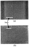
(a) Polymeric re-entrant honeycomb membrane; (b) polymeric conventional honeycomb membrane. Pores are approximately 1 mm in width (along the x direction). The membranes were fabricated by direct femtosecond laser ablation in air, with pulses at 790 nm (170 fs). Provided with permission from American Chemical Society [55].
Figure 7
Figure 7
SEM images of (a,b) the obtained membrane with a well-distributed ordered cylindrical straight through-pore structure (pore size: 2 μm, distance between adjacent pores: 2 μm) in a large area from the imprint process, and (c) the bending of the membrane edge for clearly observing the through-pores. Provided with permission from IOPScience [56].
Figure 8
Figure 8
Mechanical properties of electrospun PES membranes as a function of the mixed solvent: (a) Young’s modulus, (b) ultimate tensile strength, and (c) strain at break. Provided with permission from Elsevier [34].
Figure 9
Figure 9
Water contact angles for oxidized (a) and untreated (b) electrospun PES membranes. Provided with permission from Elsevier [34].
Figure 10
Figure 10
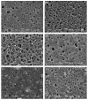
SEM images of the top surface morphology of the membranes with different TiO2 content: (A1) 0 wt.%, (B1) 1 wt.%, (C1) 2 wt.%, (D1) 3 wt.%, (E1) 4 wt.% and (F1) 5 wt.%. Provided with permission from Elsevier [90].
Figure 11
Figure 11
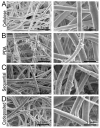
(A) SEM micrographs of the cellulose nanofiber mats used as the base materials for this study. The morphologies of (B) PDA and (C,D) polyMPC/PDA (sequential and co-deposited) functionalized nanofiber mats are also displayed. Provided with permission from American Chemical Society [130].
Figure 12
Figure 12
SEM of the modified membranes (A,B) PANi-PA membrane; (C,D) Gr/PANi-PA membrane) after use in EMBR. (A,C) ×10,000, (B,D) ×10,000. Provided with permission from Elsevier [131].
Figure 13
Figure 13
Membrane rejection properties based on surface functionalization. Provided with permission from American Chemical Society [140].

References

    1. Liquid Filtration Market. Markets and Markets: 2019; Report Number: CH 6693.
    1. Samatya S., Kabay N., Yüksel Ü., Arda M., Yüksel M. Removal of nitrate from aqueous solution by nitrate selective ion exchange resins. React. Funct. Polym. 2006;66:1206. doi: 10.1016/j.reactfunctpolym.2006.03.009. - DOI
    1. Qin L., Vervuurt S.J.N., Elmes R.B.P., Berry S.N., Proschogo N., Jolliffe K.A. Extraction and transport of sulfate using macrocyclic squaramide receptors. Chem. Sci. 2020;11:201. doi: 10.1039/C9SC04786G. - DOI
    1. Kim S., Nham J., Jeong Y.S., Lee C.S., Ha S.H., Park H.B., Lee Y. Biomimetic Selective Ion Transport through Graphene Oxide Membranes Functionalized with Ion Recognizing Peptides. J. Chem. Mater. 2015;27:1255. doi: 10.1021/cm504212j. - DOI
    1. Coskun H., Aljabour A., De Luna P., Farka D., Greunz T., Stifter D., Kus M., Zheng X., Liu M., Hassel A.W., et al. Biofunctionalized conductive polymers enable efficient CO2 electroreduction. Sci. Adv. 2017;3:e1700686. doi: 10.1126/sciadv.1700686. - DOI - PMC - PubMed

LinkOut - more resources