

CFD-Based Physical Failure Modeling of Direct-Drive Electro-Hydraulic Servo Valve Spool and Sleeve
- PMID: 36236660
- PMCID: PMC9570538
- DOI: 10.3390/s22197559
CFD-Based Physical Failure Modeling of Direct-Drive Electro-Hydraulic Servo Valve Spool and Sleeve
Abstract
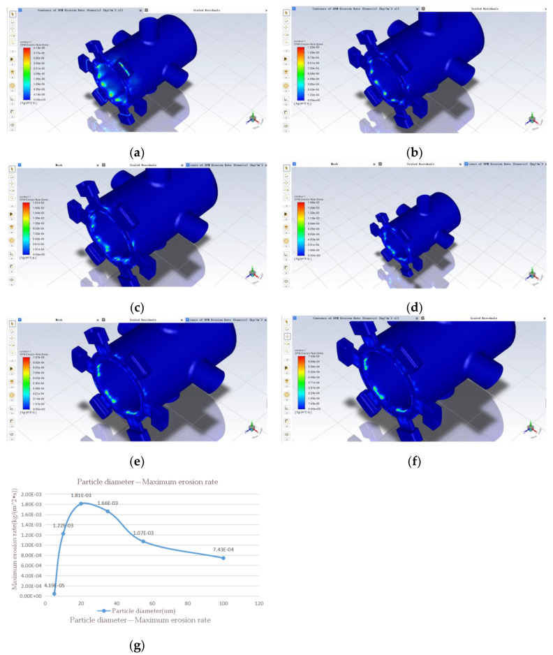
Direct-drive electro-hydraulic servo valves are used extensively in aerospace, military and control applications, but little research has been conducted on their service life and physical failure wear. Based on computational fluid dynamics, the main failure forms of direct-drive electro-hydraulic servo valves are explored using their continuous phase flow and discrete phase motion characteristics, and then combined with the theory of erosion for calculation. A mathematical model of the direct-drive electro-hydraulic servo valve is established by using Solidworks software, and then imported into Fluent simulation software to establish its physical failure model and carry out simulation. Finally, the physical failure form of the direct drive electro-hydraulic servo valve is verified by the simulation results, and the performance degradation law is summarized. The results show that temperature, differential pressure, solid particle diameter and concentration, and opening degree all have an impact on the erosion and wear of direct-drive electro-hydraulic servo valves, in which differential pressure and solid particle diameter have a relatively large impact, and the servo valve must avoid working in the range of high differential pressure and solid particle diameter of 20-40 um as far as possible. This also provides further theoretical support and experimental guidance for the industrial application and life prediction of electro-hydraulic servo valves.
Keywords: CFD; direct-drive servo valve; erosion and wear; fluent simulation; physical failure model.
Conflict of interest statement
The authors declare no conflict of interest.
Figures


References
-
- Su D.H., Ren D.L., Yang J.L. Comparison of Electro-hydraulic Proportional Valve and Electro-hydraulic Servo Valve on Performances. Hydraul. Pneum. Seals. 2008;4:1–4. (In Chinese with English abstract)
-
- Zhao C. Research and application of direct-acting electro-hydraulic servo valves. Chin. Hydraul. Pneum. 2011;12:77–79. (In Chinese)
-
- Zhang K., Yao J.Y., Jiang T.M., Yin X.Z. Durability Simulation of Electro-Hydraulic Servo Valve under Contaminant Wear with CFD. Chin. Hydraul. Pneum. 2014;4:54–59. doi: 10.11832/j.issn.1000-4858.2014.04.014. (In Chinese with English abstract) - DOI
-
- Zhang H., Xiong S.B., Liang Y.W., Xiong X. Analyses of erosion wear characteristic and structure research on hydraulic valve. J. China Coal Soc. 2008;2:214–217. doi: 10.1177/2057150X16633580. (In Chinese with English abstract) - DOI
-
- Amirante R., Distaso E., Tamburrano P. Sliding spool design for reducing the actuation forces in direct operated proportional directional valves:Experimental validation. Energy Convers. Manag. 2016;119:399–410. doi: 10.1016/j.enconman.2016.04.068. - DOI
Grants and funding
LinkOut - more resources
Full Text Sources
Miscellaneous
