. 2022 Oct 18;9(1):72.
doi: 10.1186/s40658-022-00501-y.

TriDFusion (3DF) image viewer

Affiliations

TriDFusion (3DF) image viewer

Daniel Lafontaine et al. EJNMMI Phys. .

Abstract

Background: An open-source, extensible medical viewing platform is described, called the TriDFusion image viewer (3DF). The 3DF addresses many broad unmet needs in nuclear medicine research; it provides a viewer with several tools not available in commercial nuclear medicine workstations, yet invaluable for imaging in research studies.

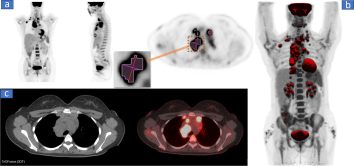
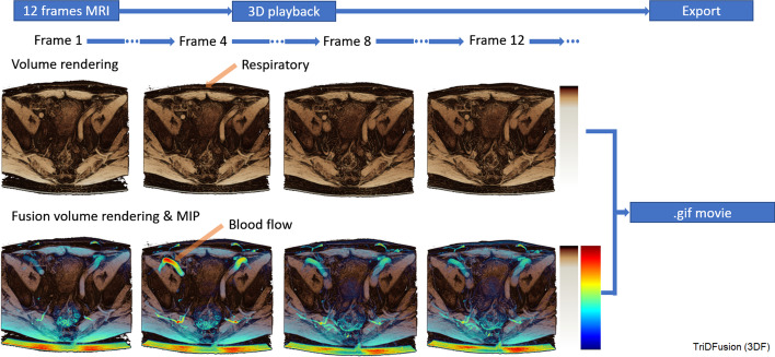
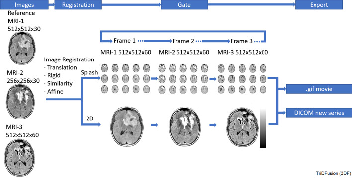
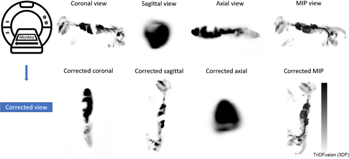
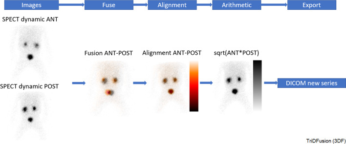
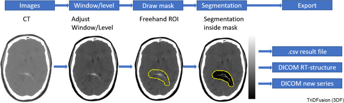
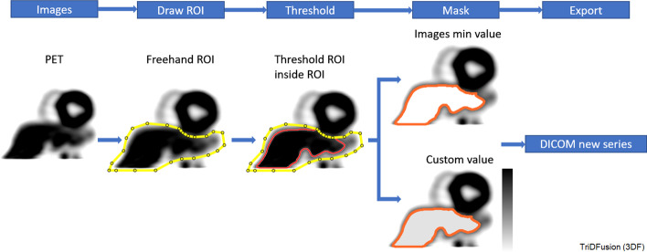
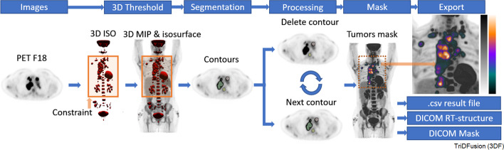
Results: The 3DF includes an image integration platform to register images from multiple imaging modalities together with delineated volumes of interest (VOIs), structures and dose distributions. It can process images from different vendors' systems and is therefore vendor neutral. The 3DF also provides a convenient tool for performing multi-modality image analysis and fusion. The functional components currently being distributed is open-source code that includes: (1) a high quality viewer that can display axial, coronal, and sagittal tomographic images, maximum intensity projection images, structure contours, and isointensity contour lines or dose colorwash, (2) multi-image fusion allowing multiple images to be fused with VOI and dose distributions, (3) a suite of segmentation tools to edit and/or create tumor and organ VOIs, (4) dosimetry tools for several radioisotopes, (5) clinical tools for correcting acquisition errors, including patient orientation, and (6) the ability to save the resultant image and VOI as DICOM files or to export the numerical results as comma separated values files. Because the code is written in MATLAB™, it is highly readable and is easier for the coder to make changes compared to languages such as C or C++. In what follows, we describe the content of the new TriDFusion (3DF) image viewer software platform using examples of a number of clinical research workflows. Such examples vary in complexity but illustrate the main attributes of the software.

Conclusions: In summary, 3DF provides a powerful, convenient, easy-to-use suite of open-source imaging research tools for the nuclear medicine community that allows physicians, medical physicists, and academic researchers to display, manipulate, and analyze images.

Keywords: DICOM viewer; Medical image manipulation; Molecular imaging software.


Conflict of interest statement

The authors declare no competing interests.

Figures

Fig. 1
Fig. 1
a The standard coronal, sagittal, and axial positron emission tomography (PET) displays in grayscale with segmented volumes of interest. The maximum intensity projection displayed in b is fused with the isosurfaces. Note the RESIST distance tool shown in the exploded view. c The transaxial computed tomography (CT) and PET/CT fusion images
Fig. 2
Fig. 2
The main ribbon and pull-down menu panels. Ribbon a on top. Below the ribbon are the various tools from left to right: b image editing, c contour segmentation, d kernel, and e the three-dimensional rendering. Selected features from these panels are shown in Table 2 and discussed in “Select features from these p” section
Fig. 3
Fig. 3
A three-dimensional volume rendered view of a four-dimensional magnetic resonance imaging sequence of the soft tissue in the pelvis (row 1) fused with a maximum intensity projection (row 2) to simultaneously highlight respiratory motion and blood flow
Fig. 4
Fig. 4
Image fusion workflow using computed tomography (CT) and positron emission tomography (PET) images
Fig. 5
Fig. 5
Image registration workflow to create a flipbook using three separate magnetic resonance images (MRIs)
Fig. 6
Fig. 6
Image resampling workflow using two computed tomography (CT) images
Fig. 7
Fig. 7
Image orientation correction workflow using a positron emission tomography image of a monkey acquired in the lateral position. Top row: reference images before reorientation using TriDFusion (3DF) image viewer; the listed orientation is incorrect. Bottom row: reference images after reorientation; the listed orientation is correct. MIP, maximum intensity projection
Fig. 8
Fig. 8
Workflow to create a geometric mean image using two single-photon emission computed tomography (SPECT) images. ANT, anterior; POST, posterior
Fig. 9
Fig. 9
The workflow to isolate blood from the surrounding tissue. The sequential steps for blood pool segmentation are shown from left to right. The yellow border indicates the constraint, and the isolated voxels are depicted on the right. CT, computed tomography; ROI, region of interest
Fig. 10
Fig. 10
Lung segmentation workflow of a computed tomography (CT) image segmented using the lung segmentation tool. The workflow illustrates how the resultant image (bronchi) is then segmented using the contour tool or the three-dimensional isosurface tool and exported. VOI, volume of interest
Fig. 11
Fig. 11
Image edge detection workflow for fusion of misaligned image using a constraint (orange box) of computed tomography (CT)-1 fused with CT-2 to resolve the misalignment
Fig. 12
Fig. 12
The workflow to remove confounding structures. The example depicts a heart/liver mask using positron emission tomography (PET) images. The yellow border indicates a constraint whereas the orange border indicates a contour created by a threshold. The gray area indicates the mask of the contour. ROI, region of interest
Fig. 13
Fig. 13
Workflow for multi-threshold segmentation using the contour tool on a positron emission tomography (PET) image. The orange outline indicates a preview of the contour. The filled region (orange) is the resultant contour from a constraint (yellow) or the entire image
Fig. 14
Fig. 14
Multi-fusion of three positron emission tomography (PET) images fused with a computed tomography (CT) image of a patient with castrate-resistant metastatic prostate cancer using radiopharmaceuticals: FDHT, FDG, and DCFPyl. FDG, fluorodeoxyglucose; FDHT, fluoro-dihydrotestosterone; and DCFPyl, 18F-piflufolastat
Fig. 15
Fig. 15
Y90 dosimetry workflow using computed tomography (CT) and positron emission tomography (PET) images. DVH, dose-volume histogram; VOI, volume of interest
Fig. 16
Fig. 16
Total tumor segmentation workflow using a positron emission tomography (PET) constrained by a window. MIP, maximum intensity projection. 3D, three-dimensional
Fig. 17
Fig. 17
Three-dimensional (3D) printing workflow using a computed tomography (CT) image

References

    1. Hermes Medical Solutions, PET/SPECT/CT/MR. 2022. https://www.hermesmedicalsolutions.com/pet-ct/.
    1. MIM Software Inc., MIM Encore ®. 2022. https://www.mimsoftware.com/solutions/nuclear_medicine/encore.
    1. Siemens Medical Solutions USA, Inc., Syngo®.via for MI. 2022. https://www.siemens-healthineers.com/en-us/molecular-imaging/reading-sof....
    1. GE Healthcare, Enterprise Imaging Solutions. 2022. https://www.gehealthcare.com/products/healthcare-it/enterprise-imaging/.
    1. Mirada, Deformable Image registration software|Mirada XDTM. 2022. https://mirada-medical.com/product/mirada-xd-image-registration-software/.

LinkOut - more resources