. 2022 Nov;19(11):1419-1426.
doi: 10.1038/s41592-022-01635-8. Epub 2022 Oct 24.

Resolution doubling in light-sheet microscopy via oblique plane structured illumination

Affiliations

Resolution doubling in light-sheet microscopy via oblique plane structured illumination

Bingying Chen et al. Nat Methods. 2022 Nov.

Abstract

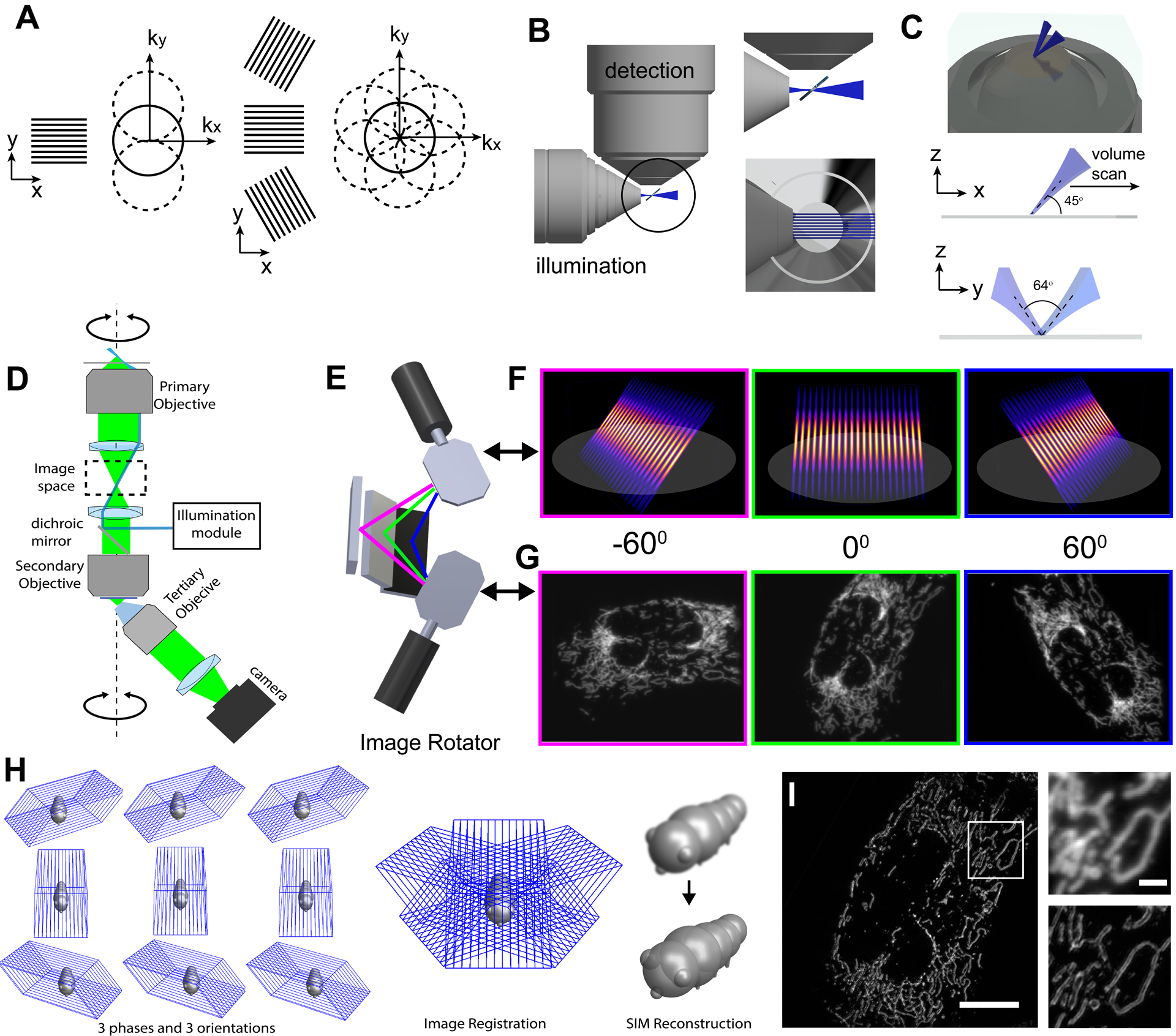
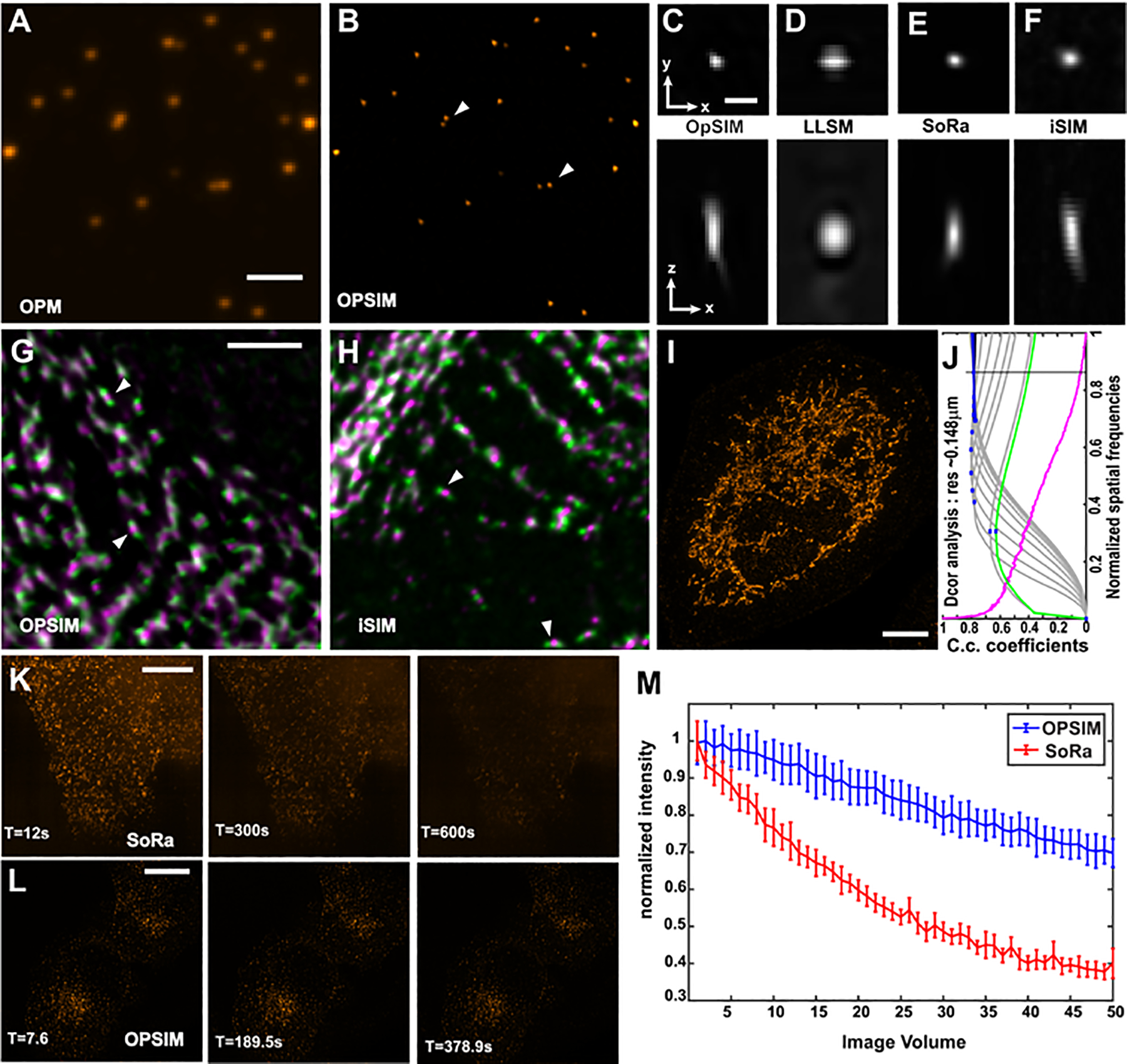
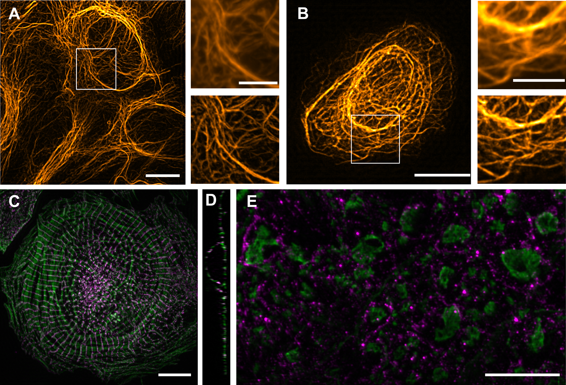
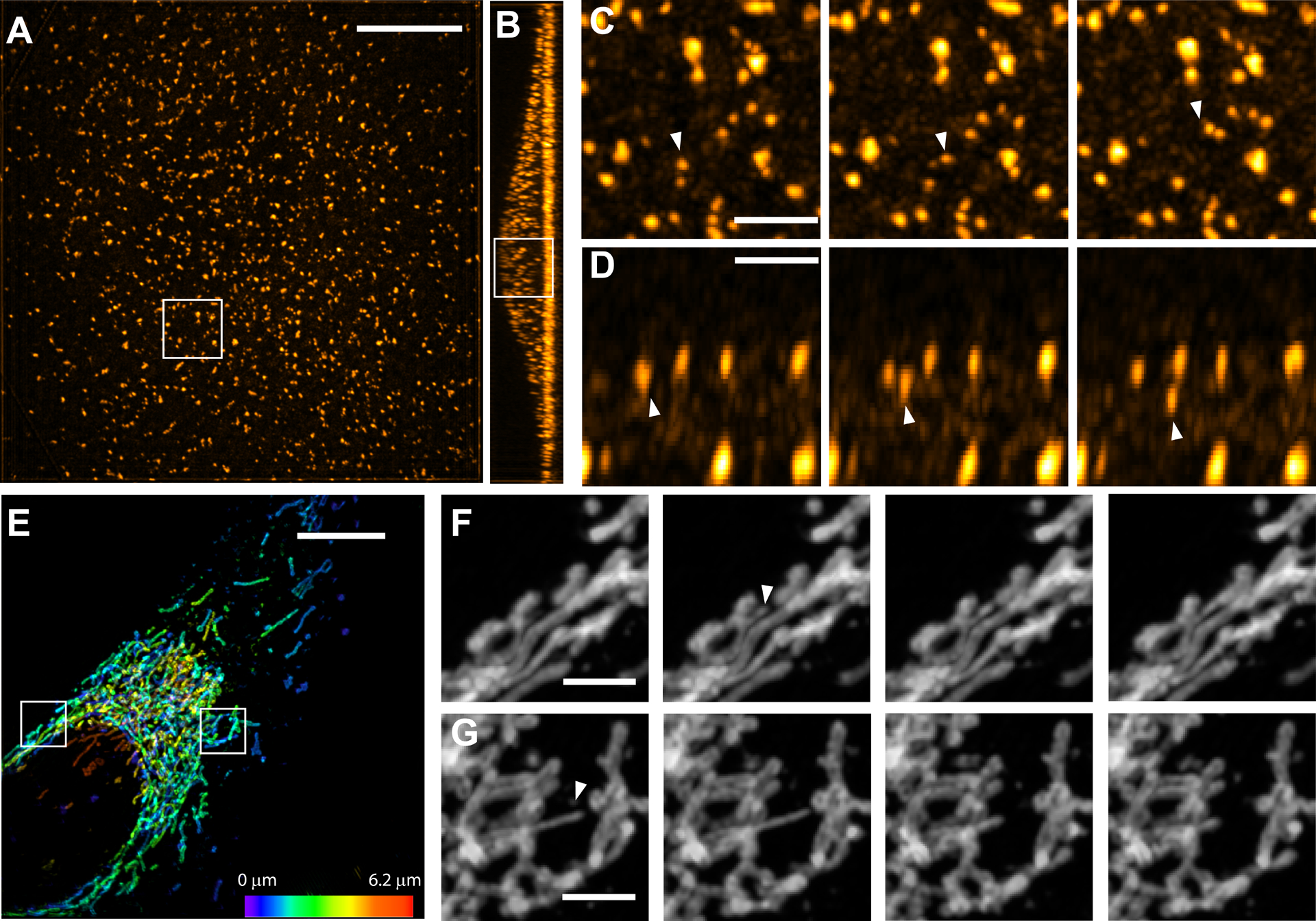
Structured illumination microscopy (SIM) doubles the spatial resolution of a fluorescence microscope without requiring high laser powers or specialized fluorophores. However, the excitation of out-of-focus fluorescence can accelerate photobleaching and phototoxicity. In contrast, light-sheet fluorescence microscopy (LSFM) largely avoids exciting out-of-focus fluorescence, thereby enabling volumetric imaging with low photobleaching and intrinsic optical sectioning. Combining SIM with LSFM would enable gentle three-dimensional (3D) imaging at doubled resolution. However, multiple orientations of the illumination pattern, which are needed for isotropic resolution doubling in SIM, are challenging to implement in a light-sheet format. Here we show that multidirectional structured illumination can be implemented in oblique plane microscopy, an LSFM technique that uses a single objective for excitation and detection, in a straightforward manner. We demonstrate isotropic lateral resolution below 150 nm, combined with lower phototoxicity compared to traditional SIM systems and volumetric acquisition speed exceeding 1 Hz.


Conflict of interest statement

Competing Interests

R.F., B.C. and B.J.C. have filed a patent for the image rotator and applications to microscopy.

Figures

Figure 1 -
Figure 1 -. Combination of structured illumination and light-sheet microscopy.
A Working principle of structured illumination microscopy (SIM): Spatial Fourier components observed by a conventional microscope lie within the solid line circle (i.e., within the passband of the microscope). Using one-dimensional structured illumination (black stripes), additional sample information can be encoded via frequency mixing (dotted circles). Using three differently oriented illumination patterns allows near-isotropic resolution improvement. B Geometry of a light-sheet microscope with numerical apertures of 0.7 and 1.1 for illumination and detection. The illumination objective can generate a structured light-sheet, but rotation of illumination pattern as shown in A is not possible. C Oblique plane microscopy (OPM) using a structured light-sheet. Two mutually coherent light-sheets form an interference pattern along a plane tilted to the coverslip. Volumetric sample information is acquired by scanning the light-sheet laterally. D Simplified optical train of an OPM: fluorescence light (green) from the oblique light-sheet (blue) is imaged onto a camera via remote focusing using a secondary and tilted tertiary objective. Arrows indicate rotation of the light-sheet and the detection path. E Schematic depiction of the image rotator, which is used in lieu of mechanical rotation of the light-sheet and detection optics. Depending on optical path selection (magenta, green and blue lines), an image rotation of −60,0 and 60 degrees around the optical axis results. F Schematic depiction of azimuthal rotation of the structured oblique light-sheets by the image rotator. G Maximum intensity projections of an U2OS cell labeled for GFP-OMP25 imaged volumetrically under three different orientations of the structured oblique light-sheet. H For Oblique plane structured illumination microscopy (OPSIM), three stacks under different phases of the structured light-sheet are acquired for each azimuthal orientation. The different orientations are computationally registered to each other, and a SIM reconstruction is performed. I Mitochondria labeled with GFP-OMP25 in an U2OS cell as imaged by OPSIM. The insets show enlarged versions of the boxed area in I, as imaged by OPM (above) and OPSIM (below). Scale Bars: G and I: 10 microns; inset in I: 2 microns.
Figure 2 –
Figure 2 –. Resolution and performance of oblique plane structured illumination microscopy.
A-B 100nm fluorescent microspheres as imaged with oblique plane microscopy (OPM) and with oblique plane structured illumination microscopy (OPSIM), respectively. White triangles point at two closely spaced beads that are only resolved with OPSIM. C-F Point spread functions for OPSIM, lattice light-sheet microscopy with one-directional structured illumination, a SoRa spinning disk, and an instant structured illumination microscope (iSIM). G&H Myosin IIA-GFP motors (green) and Myosin IIA rods (magenta, Alexa 561-conjugated antibody) in a cardiomyocyte as imaged with OPSIM and iSIM. White triangles point at Myosin motor pairs with an interdigitated rod domain that are resolved by each imaging modality. I A U2OS cell immunofluorescently labeled for MIC60 with Alexa 488 and imaged with OPSIM (maximum intensity projection). J Decorrelation analysis of the cell shown in I. Green line: decorrelation function before high-pass filtering, gray lines: decorrelation functions with high-pass filtering, blue dots: local maxima, magenta line: radial average of power spectrum of I, C.c.: cross-correlation. K Clathrin coated vesicles, labeled for AP2-eGFP, volumetrically imaged over 50 timepoints with a SoRa spinning disk. L Clathrin coated vesicles, labeled with AP2-eGFP, imaged over 50 timepoints using OPSIM. M Normalized fluorescence intensities of the 20 brightest vesicles over time for OPSIM and SoRa imaging. Scale bars: A,G 2 microns; C 500nm; I,K,L 10 microns.
Figure 3 –
Figure 3 –. Imaging of cellular samples with OPSIM.
A The actin cytoskeleton in an hTERT RPE cell as imaged by OPMSIM. Insets show the boxed region in A, as imaged by OPM (above) and OPSIM (below). B Vimentin in an hTERT RPE-1 cell as imaged by OPMSIM. The insets show enlarged versions of the boxed area in B, as imaged by OPM (above) and OPSIM (below). C Cardiomyocyte labeled for actin (green, Alexa Fluor 488-phalloidin) and alpha-actinin 2 (magenta, Alexa 561-conjugated antibody), as imaged by OPSIM. D Cross-sectional view (single slice) of the cardiomyocyte shown in C. E Spinal cord slice, immunofluorescently labeled for neurofilament (green) and myelin (magenta), as imaged by OPSIM. A,B,C,E show maximum intensity projections. Scale bars: A,B,C,E: 10 microns; insets of A and B: 5 microns.
Figure 4 –
Figure 4 –. Dynamic volumetric imaging with OPSIM.
A An ARPE-19 cell, labeled for AP2-eGFP, as imaged volumetrically by OPSIM at 0.86Hz. A maximum intensity projection is shown. B cross sectional view of the ARPE cell in A (maximum intensity projection). C Three selected timepoints of the boxed area in A. Temporal separation between each slice is 3.5s D Three selected timepoints of the boxed area in B. Temporal separation between each slice is 2.3s White triangles point at movement of a clathrin coated vesicle. E Mitochondria in an U2OS cell, as imaged by OPSIM at a volumetric rate of 1.2 Hz. Maximum intensity projection with height above the coverslip encoded in color. F Selected timepoints of the boxed region on the left in E. Temporal separation between each slice is 0.82s. White triangle marks the tip of a protruding mitochondrion. G Selected timepoints of the boxed region on the right in E. Temporal separation between each slice is 1.64s White triangle marks the tip of a retracting mitochondrion. Scale Bars: A,E: 10 microns. C-D, F-G: 2 microns.

Similar articles

Cited by

References

    1. Liu Z, Lavis, Luke D & Betzig E Imaging Live-Cell Dynamics and Structure at the Single-Molecule Level. Molecular Cell 58, 644–659 (2015). - PubMed
    1. Stelzer EHK et al. Light sheet fluorescence microscopy. Nature Reviews Methods Primers 1, 73 (2021).
    1. Reynaud EG, Kržič U, Greger K & Stelzer EHK Light sheet‐based fluorescence microscopy: More dimensions, more photons, and less photodamage. HFSP Journal 2, 266–275 (2010). - PMC - PubMed
    1. Olarte OE, Andilla J, Gualda EJ & Loza-Alvarez P Light-sheet microscopy: a tutorial. Advances in Optics and Photonics 10 (2018).
    1. Stelzer EHK Light-sheet fluorescence microscopy for quantitative biology. Nature Methods 12, 23–26 (2014). - PubMed

Publication types