. 2022 Oct 25;10(1):e2204315.
doi: 10.1002/advs.202204315. Online ahead of print.

Direct Formation of Hard-Magnetic Tetrataenite in Bulk Alloy Castings

Affiliations

Direct Formation of Hard-Magnetic Tetrataenite in Bulk Alloy Castings

Yurii P Ivanov et al. Adv Sci (Weinh). .

Retraction in

Abstract

Currently, predominant high-performance permanent magnets contain rare-earth elements. In the search for rare-earth-free alternates, body-centered tetragonal Fe-Ni is notable. The ordering to form this phase from the usual cubic close-packed Fe-Ni is understood to be possible only below a critical temperature, commonly accepted to be 593 K. The ordering is first demonstrated by using neutron irradiation to accelerate atomic diffusion. The tetragonal phase, designated as the mineral tetrataenite, is found in Fe-based meteorites, its formation attributed to ultra-slow cooling. Despite many attempts with diverse approaches, bulk synthesis of tetrataenite has not been reported. Here it is shown that with appropriate alloy compositions, bulk synthesis of tetrataenite is possible, even in conventional casting at cooling rates 11-15 orders of magnitude higher than in meteorites. The barrier to obtaining tetrataenite (slow ordering from cubic close-packed to body-centered tetragonal) is circumvented, opening a processing window for potential rare-earth-free permanent magnets. The formation of tetrataenite on industrially practicable timescales also throws into question the interpretation of its formation in meteorites and their associated cooling rates.

Keywords: meteorite; order-disorder; rare-earth-free permanent magnet; tetrataenite.


Conflict of interest statement

The authors declare no conflict of interest.

Figures

Figure 1
Figure 1
As‐cast Fe‐Ni‐(P,C) alloys. a) Examples of a 3 mm diameter rod and a 15 mm diameter button. Microstructures: scanning‐electron micrographs of polished sections of such samples show primary dendrites of an Fe‐Ni phase (tetrataenite) in a eutectic matrix within which the metalloids (P,C) are concentrated. With decreased metalloid content, the primary‐phase volume fraction increases (Table 2). b) lateral section of 1 mm diameter rod of Fe50Ni30P13C7 (at.%). Longitudinal sections of c) 3 mm rod of Fe50Ni30P13C7; d) 3 mm rod of Fe53Ni32P9.75C5.25; e) button of Fe55Ni35P6.5C3.5; f) button of Fe58.5Ni38.5P3. In all cases, electron diffraction shows the primary phase to be ordered L10, not the expected chemically disordered cubic close‐packed solid solution.
Figure 2
Figure 2
Composition mapping of an Fe50Ni30P13C7 as‐cast 1 mm diameter rod. a) high‐angle annular dark‐field (HAADF) image and energy‐dispersive X‐ray spectroscopy (EDX) maps of a region showing the near‐circular section of a dendrite side‐arm. In a row of such sections, they all share the same crystallographic orientation, consistent with the single‐crystal nature of each dendrite. b) superposition of the P and C maps shows that the eutectic matrix consists of three phases: a phosphide, a carbide, and (arrowed) the same Fe–Ni phase as is found in the primary dendrites. The microstructure in this rod is shown in Figure 1b and the corresponding X‐ray diffractogram (“as‐cast”) in Figure 3a,b.
Figure 3
Figure 3
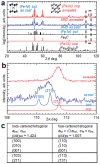
X‐ray diffraction analysis (CoKα radiation) of Fe50Ni30P13C7 (at.%) alloy. a) Traces (from a lateral section of 1 mm diam. rod) are shown for the as‐cast sample and after annealing at 1123 K for 15 min. Expected patterns are shown at the bottom. Those for (Fe50Ni50)3P and Fe3C are from tabulated data for the stoichiometric phases. Those for ccp and L10 are for lattice parameters adjusted to match the measured diffractograms. b) A close‐up of the angular range indicated by the dashed box in (a). This Bragg peak is split in the as‐cast sample and single after annealing. The splitting indicates tetragonality associated with the L10‐type ordering of iron and nickel atoms. c) Comparison of the basis vectors for the L10 phase described according to the conventional body‐centered tetragonal unit cell and the unconventional face‐centered tetragonal cell. Examples of equivalent Miller indices (hkl) are given for the two cells. The axial ratio (c/a)fct is ≈1.007 for the tetrataenite in the present work, and is one when disordered into the ccp (A1) structure.
Figure 4
Figure 4
Transmission electron microscopy of the primary Fe‐Ni phase within as‐cast Fe50Ni30P13C7. This is from the same rod as considered in Figure 2. a) Selected‐area electron diffraction (SAED) on the [110] zone axis; b) intensity profiles along the solid and dashed lines in (a). c) High‐resolution scanning TEM (STEM) image on the same [110] zone axis; d) intensity profiles along the solid and dashed lines in (c).
Figure 5
Figure 5
Order‐disorder transition in Fe‐Ni. a) Tetragonality c/a of the Fe‐Ni primary phase extracted from a Fe55Ni35P6.5C3.5 (at.%) button, measured in‐situ in TEM during heating (closed circles) and cooling (open circles) following the profile in b). c,d) Before‐and‐after selected‐area electron diffraction patterns at room temperature from the thin foil used for in‐situ TEM: (c) as‐cast, showing L10; (d) after heating and cooling, showing ccp. In c), four weak reflections, one circled for emphasis, indicate that the iron and nickel atoms are distributed non‐randomly, forming the L10 structure.
Figure 6
Figure 6
Magnetic domains in L10 and ccp phases. a) Bright‐field TEM image of the thin foil used to obtain the results in Figure 5. b‒e) Differential phase contrast imaging, mapping the magnitude of orthogonal components of magnetization B x and B y at remanence: b,c) for the sample in a); d,e) for a sample of ccp Fe60Ni40. In c), the arrow indicates the magnetization vector, projected into the plane of the micrograph; the magnetic structure is single‐domain with high remanent magnetization, parallel to the c‐axis of the L10 structure (see schematic). In (d,e), the multidomain structure has near‐zero remanent magnetization.

References

    1. Lewis L. H., Mubarok A., Poirier E., Bordeaux N., Manchanda P., Kashyap A., Skomski R., Goldstein J., Pinkerton F. E., Mishra R. K., Kubic Jr R. C., Barmak K., J. Phys. Condens. Matter 2014, 26, 064213. - PubMed
    1. Cui J., J. M. K., Zhou L., Liu F., Gabay A., Hadjipanayis G., Balasubramanian B., Sellmyer D., Acta Mater. 2018, 158, 118.
    1. Paulevé J., Dautreppe D., Laugier J., Néel L., J. Phys. Radium 1962, 23, 841.
    1. Petersen J. F., Aydin M., Knudsen J. M., Phys. Lett. 1977, 62A, 192.
    1. Clarke Jr R. S., Scott E. R. D., Amer. Mineral. 1980, 65, 624.

Publication types

LinkOut - more resources