

Simultaneous PSI-Based Orthognathic and PEEK Bone Augmentation Surgery Leads to Improved Symmetric Facial Appearance in Craniofacial Malformations
- PMID: 36294792
- PMCID: PMC9605459
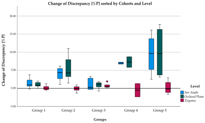
- DOI: 10.3390/jpm12101653
Simultaneous PSI-Based Orthognathic and PEEK Bone Augmentation Surgery Leads to Improved Symmetric Facial Appearance in Craniofacial Malformations
Abstract
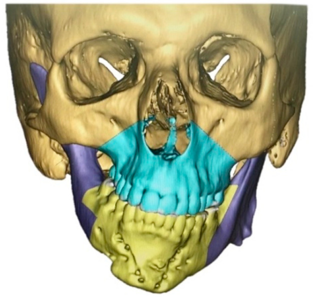
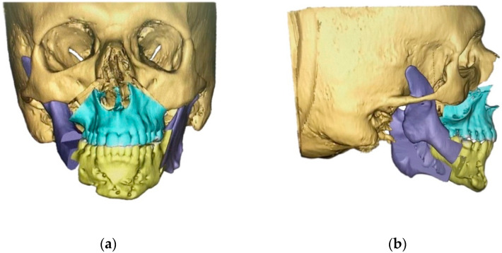
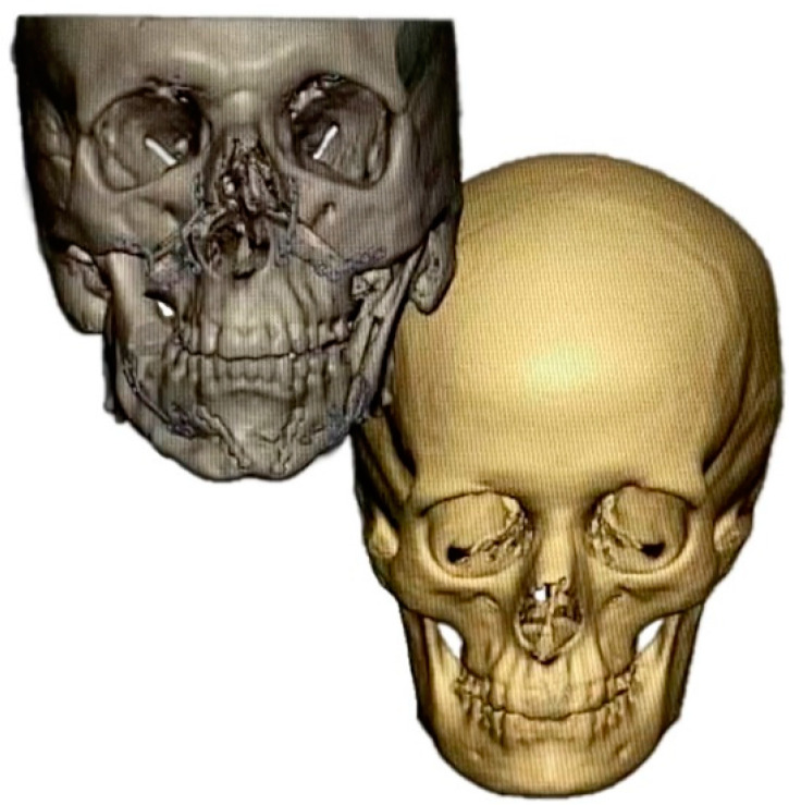
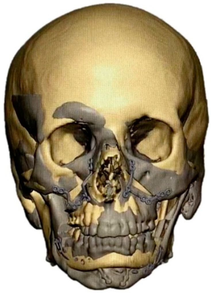
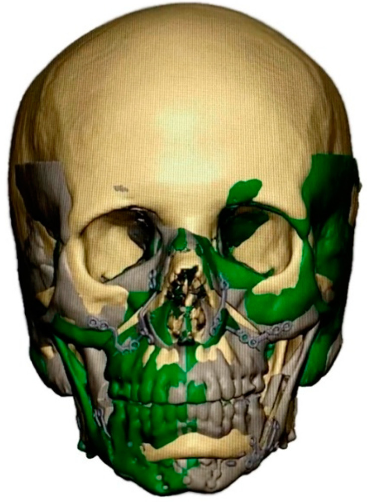
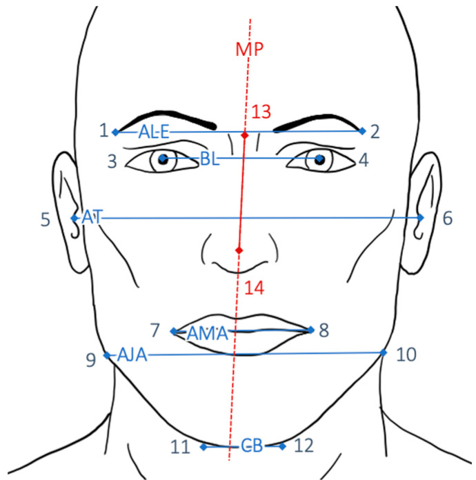
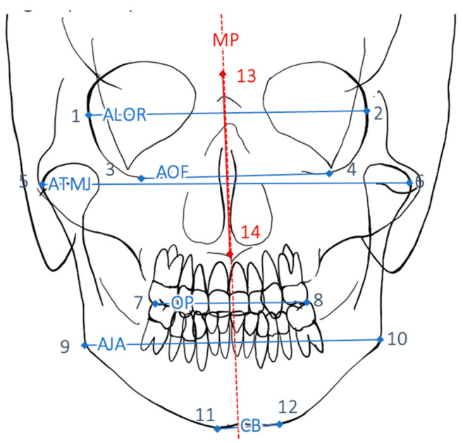
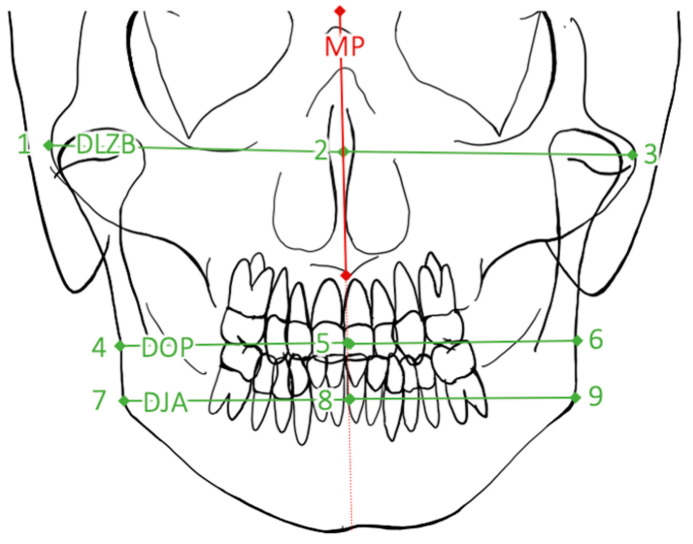
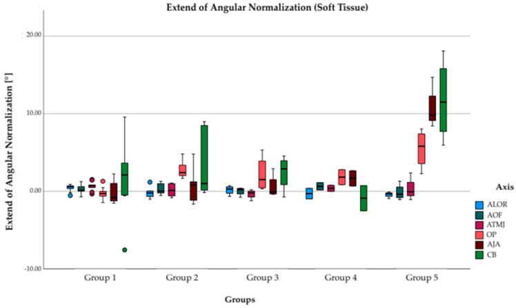
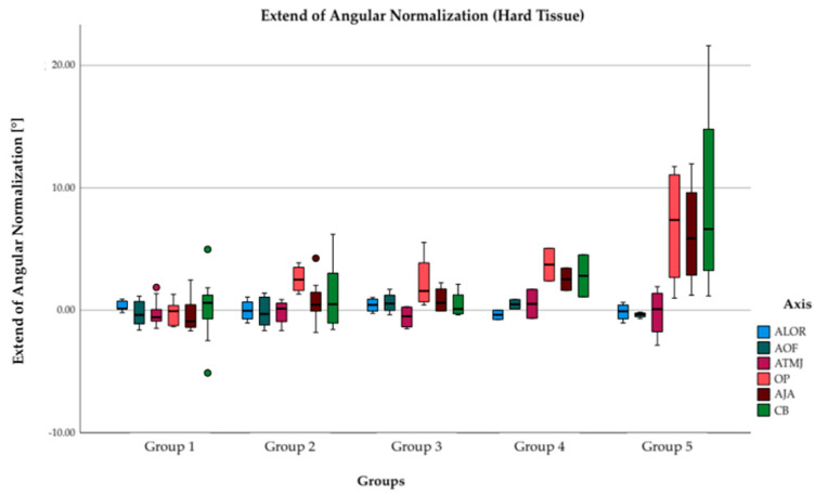
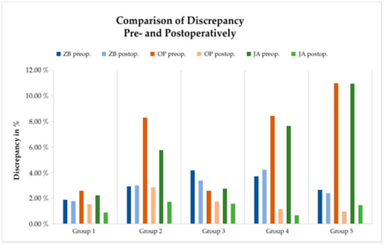
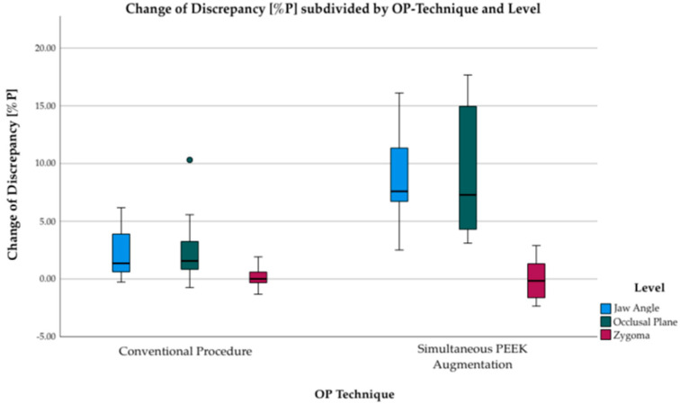
(1) The aim of the present study was to compare the outcome of facial symmetry after simultaneous digitally planned patient-specific implant (PSI-) based orthognathic surgery and polyether ether ketone (PEEK) bone augmentation in patients with craniofacial malformations. (2) To evaluate the outcome of the two different surgical approaches (conventional PSI-based orthognathic surgery versus simultaneous PSI-based orthognathic surgery with PEEK bone augmentation), a comparison of five different groups with a combination of the parameters (A) with vs. without laterognathia, (B) syndromic vs. non-syndromic, and (C) surgery with vs. without PEEK bone augmentation was conducted. The digital workflow comprised cone beam CT (CBCT) scans and virtual surgery planning for all patients in order to produce patient specific cutting guides and osteosynthesis plates. Additionally, deformed skulls were superimposed by a non-deformed skull and/or the healthy side was mirrored to produce PSI PEEK implants for augmentation. Retrospective analyses included posterior-anterior conventional radiographs as well as en face photographs taken before and nine months after surgery. (3) Simultaneous orthognathic surgery with PEEK bone augmentation significantly improves facial symmetry compared to conventional orthognathic surgery (6.5%P (3.2-9.8%P) (p = 0.001). (4) PSI-based orthognathic surgery led to improved horizontal bone alignment in all patients. Simultaneous PEEK bone augmentation enhanced facial symmetry even in patients with syndrome-related underdevelopment of both soft and hard tissues.
Keywords: PEEK; craniofacial malformation; craniofacial reconstruction; digital workflow; orthognathic surgery; patient-specific implants.
Conflict of interest statement
The authors declare no conflict of interest.
Figures
References
-
- Kronmiller J.E. Seminars in Orthodontics. Elsevier; Amsterdam, The Netherlands: 1998. Development of asymmetries. - PubMed
-
- Cao J., Shen S., Liu Z., Dai J., Wang X. Evaluation of mandibular symmetry in patients with condylar osteochondroma who underwent intro-oral condylar resection and simultaneous bimaxillary orthognathic surgery. J. Craniofacial Surg. 2020;31:1390–1394. doi: 10.1097/SCS.0000000000006432. - DOI - PubMed
-
- Bailey L.J., Collie F.M., White R.P., Jr. Long-term soft tissue changes after orthognathic surgery. Int. J. Adult Orthod. Orthognath. Surg. 1996;11:7–18. - PubMed
LinkOut - more resources
Full Text Sources
Research Materials
