. 2022 Nov 5;8(1):48.
doi: 10.1038/s41526-022-00235-2.

Granular piston-probing in microgravity: powder compression, from densification to jamming

Affiliations

Granular piston-probing in microgravity: powder compression, from densification to jamming

Olfa D'Angelo et al. NPJ Microgravity. .

Abstract

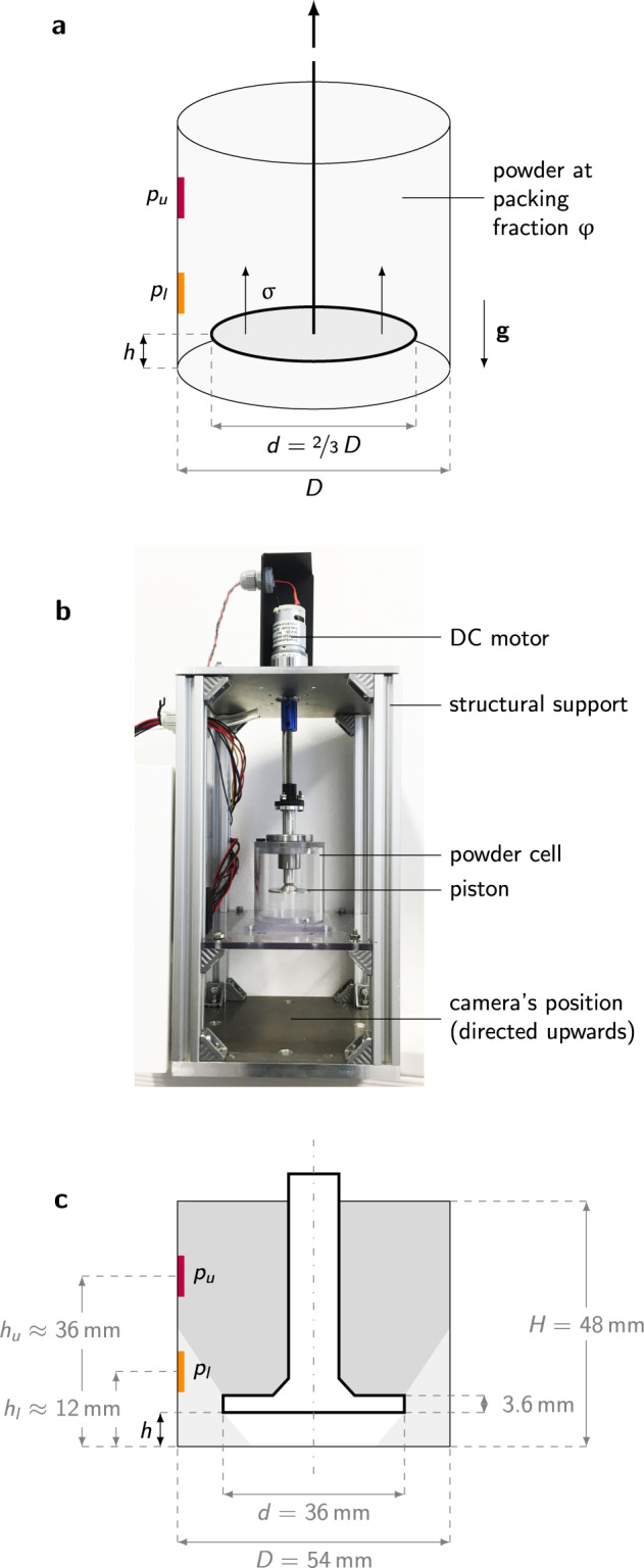
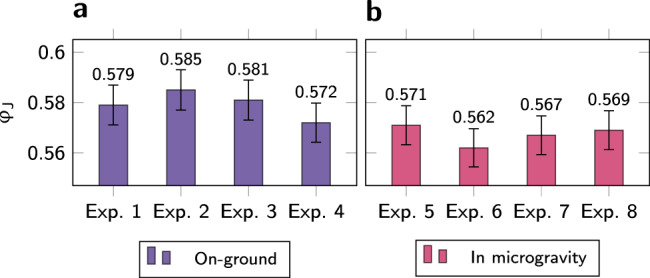
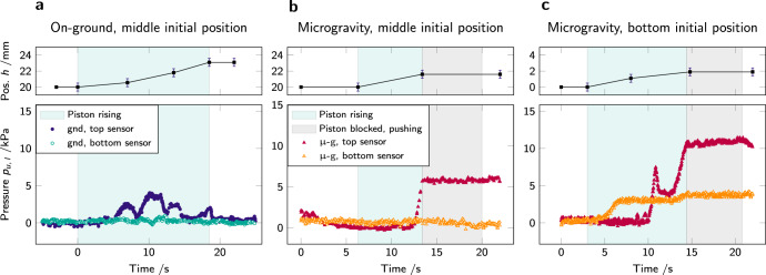
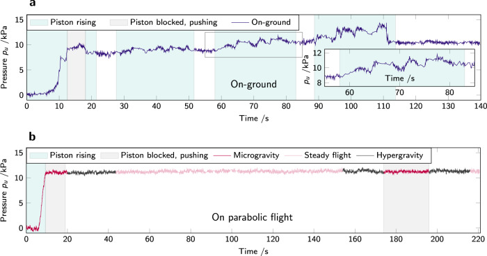
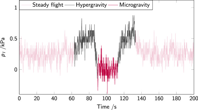
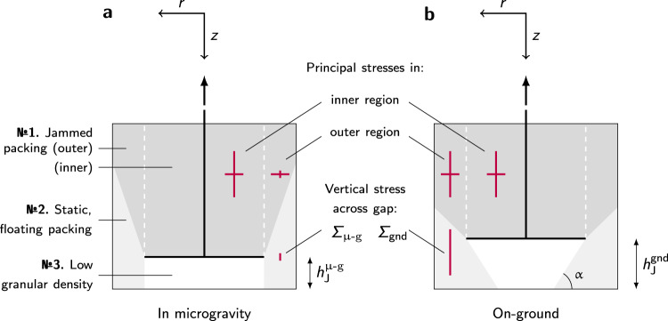
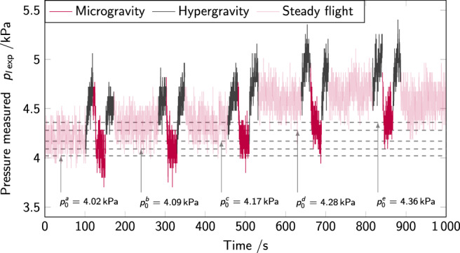
The macroscopic response of granular solids is determined by the microscopic fabric of force chains, which, in turn, is intimately linked to the history of the solid. To query the influence of gravity on powder flow behavior, a granular material is subjected to compression by a piston in a closed container, on-ground and in microgravity (on parabolic flights). Results show that piston-probing densifies the packing, eventually leading to jamming of the material compressed by the piston, regardless of the gravitational environment. The onset of jamming is found to appear at lower packing fraction in microgravity ([Formula: see text]) than on-ground ([Formula: see text]). We interpret these findings as the manifestation of a granular fabric altered by the gravitational force field: in absence of a secondary load (due to gravitational acceleration) to stimulate reorganization in a different direction to the major compression stress, the particles' configuration becomes stable at lower density, as the particles have no external drive to promote reorganization into a denser packing. This is coupled with a change in interparticular force balance which takes place under low gravity, as cohesive interactions become predominant. We propose a combination of microscopic and continuum arguments to rationalize our results.


Conflict of interest statement

The authors declare no competing interests.

Figures

Fig. 1
Fig. 1. Piston-probing setup.
a Piston-probing principle: a piston rises incrementally in a closed container, filled with powder at packing fraction φ, applying a normal stress σ on the granular packing. The pressure p transmitted through the granular material is recorded by two pressure sensors placed on the lateral walls of the container (respectively recording pu and pl, upper and lower pressures). The direction of the gravitational acceleration g is indicated by a downwards-pointing arrow. b Experimental setup, showing the container (here empty) in its support structure (photograph taken by the authors). c Schematic including container’s and piston’s dimensions (in gray), and variables recorded (in black).
Fig. 2
Fig. 2. Time evolution of piston position and pressure in powder cell.
a Piston position in height as a function of time. Error bars represent the experimental precision in optical measurement. b Pressure recorded by the top sensor during the first step up of the piston, on-ground (blue disks, gnd), and in microgravity (red triangles, μ-g). The jamming times tJ are marked by vertical dashed lines, as well as φ1 (see the body of the text) and five points of interest that correspond to c, images (i–v). (i) and (ii) are images from the bottom of the experiment cell looking up in microgravity (snapshots taken by the authors); (iii), (iv), and (v) on-ground. The piston is black and the PS powder, white. The clearly visible piston at all times in microgravity (i, ii, iii) indicates the absence of powder flow below the piston, different from the behavior on-ground (iv, v).
Fig. 3
Fig. 3. Packing fraction at jamming φJ, estimated from the height at which the piston is driven to a halt by the resistance of the packing.
Experiments are conducted in the same setup, a on-ground (gnd) and b in microgravity (μ-g). Error bars represent the formal accuracy (see Methods section for details on the calculation).
Fig. 4
Fig. 4. Pressure evolution with piston rise.
a (gnd) and b, c in microgravity (μ-g). The pressure pu, l (bottom graphs) is recorded by sensors in two positions: on the top part of the cell (pu: filled marks, gnd in blue and μ-g in red) and on the bottom part of the cell (pl: open marks, gnd in green and μ-g in orange). On a, b the piston starts in the middle of the cell (position h ≈ 20 mm), while on c it starts at the bottom of the cell (h = 0 mm): on a and b the pressure sensors are distributed one above the piston and one below, while on c both sensors are above the piston. On a t = 0 s represents the start of piston rise; on b, c, t = 0 s represents the start of the microgravity phase. The pressure evolution exhibits repeated yielding on-ground, while the packing jammed in microgravity remains stable, even at maximum load. In the top graphs, the error bars represent the experimental precision in optical measurements.
Fig. 5
Fig. 5. Pressure evolution for a duration of ≈200 s after the initial densification step leading to jamming. Pressure is recorded by the top sensor inside the powder container.
a on-ground (gnd) and b microgravity (μ-g). The inset of a is a close-up of the pressure evolution during the second step-up of the piston, where the time and pressure range expanded in the inset are highlighted on the main panel by a gray rectangle. After an initial steep rise in pressure both on-ground and in microgravity, corresponding to jamming of the granular packing, on-ground the packing yields under the stress applied by the piston rise. On the contrary, the packing jammed in microgravity remains stable against hypergravity and against pressure applied by the piston in the next microgravity period.
Fig. 6
Fig. 6. Pressure pl on the bottom sensor inside a cell filled with powder, but where the piston does not move: the pressure changes are solely due to changes in acceleration during the parabolic flight maneuvers.
Initial time t = 0 s is not a significant instant.
Fig. 7
Fig. 7. Schematic representation of the regions appearing in the container as the piston rises.
a in microgravity (μ-g) and b on-ground (gnd). On-ground, the powder forms a slope at its angle of repose α with the horizontal. Stress magnitudes in arbitrary units are depicted by red lines. The coordinate system used in the body of the text is shown above each schematic. The height hJμg,gnd denotes the height at which the piston is stopped by the jammed material above it, respectively under microgravity and on-ground conditions. The difference in force chain configuration between microgravity and ground leads to drastically different vertical stresses in the outer region. The load Σ on the material below the piston is, as a consequence, much lower in microgravity compared to the ground. See also Supplementary Material, Supplementary Figure 1.
Fig. 8
Fig. 8. Scanning electron microscopy of the granular material used.
The micrographs presented are taken in-house after the completion of the cleaning process.
Fig. 9
Fig. 9. Pressure pexp measured on the bottom sensor inside an experimental cell filled with powder but with no motion of the piston.
Pressure changes are solely due to changes in acceleration during parabolic flight maneuvers. The offset pressures found from the microgravity phases are shown as dashed lines, labeled p0a,b,c,d,e. The increase in offset pressure throughout the experiments shown here is clearly visible, amounting to +0.34 kPa in 1000 s.

References

    1. Wilkinson RA, Behringer RP, Jenkins JT, Louge MY. Granular materials and the risks they pose for success on the moon and mars. AIP Conf. Proc. 2005;746:1216–1223.
    1. Karapiperis K, Marshall JP, Andrade JE. Reduced gravity effects on the strength of granular matter: DEM simulations versus experiments. J. Geotech. Geoenviron. Eng. 2020;146:06020005.
    1. Antony, S. J. et al. Modeling the flow characteristics of granular materials under low gravity environments using discrete element method. Conference paper, 12–21 (2021).
    1. D’Angelo O, et al. A gravity-independent powder-based additive manufacturing process tailored for space applications. Addit. Manuf. 2021;47:102349.
    1. Mo P, Zhou G, Gao F, Li R. Bearing capacity of surface circular footings on granular material under low gravity fields. J. Rock Mech. Geotech. Eng. 2021;13:612–625.