. 2022 Oct 21:16:753496.
doi: 10.3389/fncir.2022.753496. eCollection 2022.

Reconstructing neural circuits using multiresolution correlated light and electron microscopy

Affiliations

Reconstructing neural circuits using multiresolution correlated light and electron microscopy

Karl Friedrichsen et al. Front Neural Circuits. .

Abstract

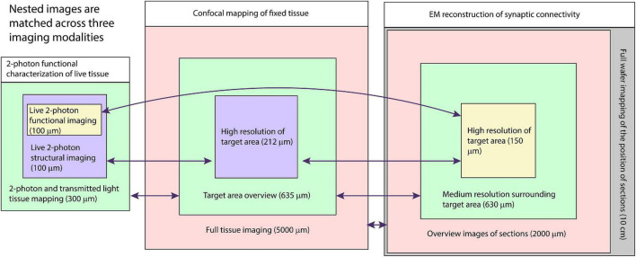
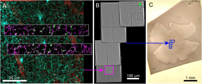
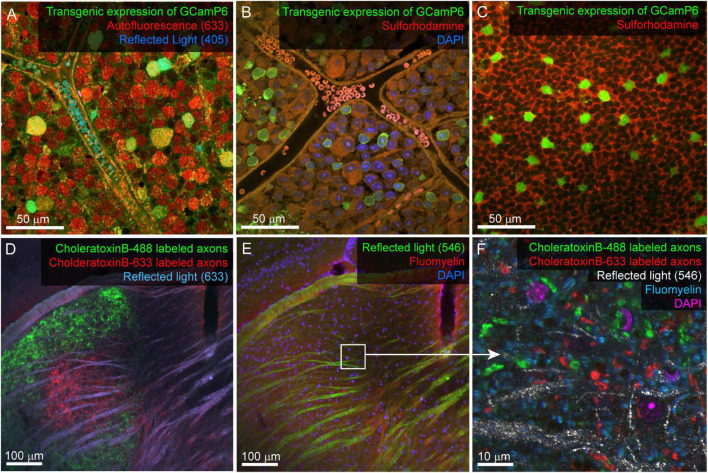
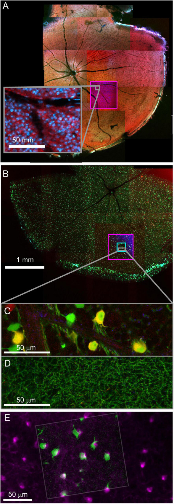
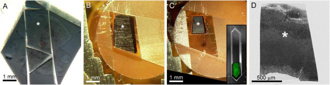
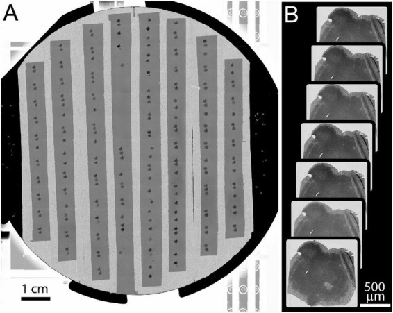
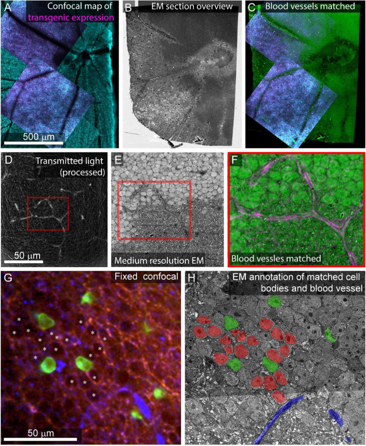
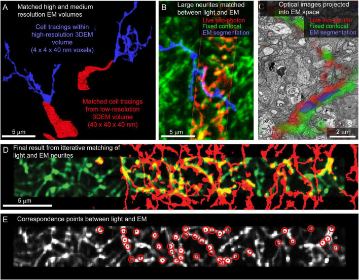
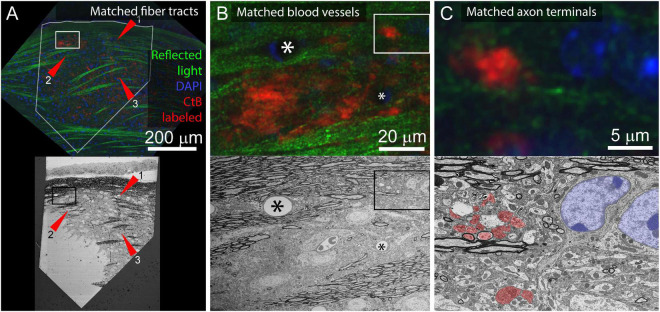
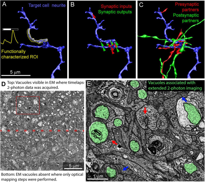
Correlated light and electron microscopy (CLEM) can be used to combine functional and molecular characterizations of neurons with detailed anatomical maps of their synaptic organization. Here we describe a multiresolution approach to CLEM (mrCLEM) that efficiently targets electron microscopy (EM) imaging to optically characterized cells while maintaining optimal tissue preparation for high-throughput EM reconstruction. This approach hinges on the ease with which arrays of sections collected on a solid substrate can be repeatedly imaged at different scales using scanning electron microscopy. We match this multiresolution EM imaging with multiresolution confocal mapping of the aldehyde-fixed tissue. Features visible in lower resolution EM correspond well to features visible in densely labeled optical maps of fixed tissue. Iterative feature matching, starting with gross anatomical correspondences and ending with subcellular structure, can then be used to target high-resolution EM image acquisition and annotation to cells of interest. To demonstrate this technique and range of images used to link live optical imaging to EM reconstructions, we provide a walkthrough of a mouse retinal light to EM experiment as well as some examples from mouse brain slices.

Keywords: confocal 3D microscopy; connectomics; correlated light and electron microscopy (CLEM); electron microscopy; neural circuit; synapse; tissue mapping.


Conflict of interest statement

The authors declare that the research was conducted in the absence of any commercial or financial relationships that could be construed as a potential conflict of interest.

Figures

FIGURE 1
FIGURE 1
Schematic of multiresolution correlated light to EM. Nested image sets are shown for live 2-photon imaging (left), confocal mapping of fixed tissue (middle), and EM of synaptic connectivity (right). Matched image scales are indicated by color. The high-resolution image stacks providing the functional and connectivity data for the targeted cells are highlighted in yellow. Arrows indicate which images are typically compared for matching between modalities.
FIGURE 2
FIGURE 2
Live imaging of a retinal explant. (A) Two-photon imaging of calcium responses (gray inset, single frame = green, time average = magenta) to visual stimuli acquired in two rectangular ROIs and at multiple depths in the retina. Functional ROIs are aligned within two-photon structural images of the surrounding transgenic expression of the calcium indicator (2-photon) in cyan and blood vessels (scanning transmitted) in red. Blood vessels in transmitted light images are enhanced using bandpass filtering. (B) Scanning transmitted light images (gray, acquired on 2-photon microscope) are used to map the position of the characterized cells (pink box) relative to the optic nerve head (green asterisk). (C) The blue boxes map the position of the gray images on the left onto the widefield transmitted image of the entire retina.
FIGURE 3
FIGURE 3
Example confocal imaging of fixed retina (top) and visual thalamus (bottom) to map features for mrCLEM. (A) Imaging of the ganglion-cell-side surface of a mouse retina (transgenic labeling green) with reflected 405 laser line (blue) and autofluorescence from the 633 laser line (red). Note clear cell bodies and vasculature. (B) Imaging of the ganglion cell layer in mouse retina (transgenic labeling green) with Sulforhodamine (red), and DAPI (blue). (C) Same tissue as (B) imaged 50 μm deeper in the inner nuclear layer. (D,E) Six-channel tissue mapping of a vibratome section of mouse dorsal lateral geniculate nucleus. (D) Retinal ganglion cell axons from the contralateral eye labeled with CtB-488 (green), and the ipsilateral eye labeled with CtB-633 (red). Fiber tracks (blue) are imaged using reflected 633 laser line. (E) Same image stack as (D), showing DAPI (blue), FluoroMyelin (red), and 546 reflected light (green). White box indicates the field of view for (F). (F) Single plane from a high-resolution image stack acquired at the white box in E. High-frequency matching features (FluoroMyelin = cyan, retinal ganglion cell synaptic boutons = red and green) are shown in the context of medium-resolution features (DAPI stained nuclei = magenta) and large-scale features (fiber tract = white).
FIGURE 4
FIGURE 4
Confocal maps of fixed tissue. Low-resolution mosaics are acquired from the whole tissue, and higher-resolution image stacks are acquired that encompass targeted regions of interest. (A) Mosaic of mouse retina stained with Sulforhodamine (red) and DAPI (blue). Pink box indicates targeting of image stack acquired with 20x objective. The gray insert provides a closer look at the images in the pink box. (B) Mosaic of mouse retina transgenically expressing GCamp6 (green) and td-tomato (red). Pink and cyan boxes indicate targeting of 20x and 60x objective image stacks. (C,D) Two planes of one high-resolution (60x) image stack with labeled cell bodies (C) and neurite plexus (D). (E) Overlay of showing the alignment of cell body signal in a 2-photon live image of GCamp6 (green) and fixed confocal image stack of GCamp6 in the same region of tissue (magenta).
FIGURE 5
FIGURE 5
The optically characterized region of interest is excised from the aldehyde fixed tissue and processed for EM. The white asterisk tracks the region of interest across panels. (A) A 2 mm × 3 mm asymmetric slab is excised from a retinal whole mount. Asterisk indicates the targeted region of interest in all panels. (B) The tissue is stained and embedded in resin (see section “Materials and methods”). (C) The block is trimmed to a trapezoid approximately 800 μm × 1200 μm centered around the optically characterized region of interest. The gray inset shows how to trim a block (extended hexagon, different tissue block) for direct-to-tape automated cutting. The green channel shows that tissue features can be obtained from wide field reflected light imaging of the surface of a trimmed block face. (D) Overview EM image of 40 nm-thick section taken from blockface in (C).
FIGURE 6
FIGURE 6
Example of full wafer image and section overview images. (A) Full wafer EM image of the 10 cm wafer is acquired as a 14 × 12 tile mosaic. (B) An overview image is acquired for each section. These overviews are then aligned to a template image to generate a 3D volume of the entire tissue.
FIGURE 7
FIGURE 7
Feature matching between optical images and low-resolution EM. (A) Multiscale confocal maps of transgenic expression (magenta) and DAPI (cyan) in fixed tissue. Note blood vessels visible by absence of staining. (B) Same tissue as (A). Section overview image (1 μm pixel size) of ultrathin section used to map tissue position on collection wafer. (C) Alignment of blood vessels between the confocal map from A (blue, red) with the section overview from (B) (green). (D) Transmitted light image of live retina filtered with edge detection to show blood vessels. Red box corresponds to the position of red box in (E,F). (E) Electron micrograph of tissue shown in (D) acquired at 40 nm pixel size. Note the blood vessel in the red box. (F) Alignment of the blood vessel shown in red boxes in panel (D) (magenta) and E (green). (G) Confocal stack of fixed tissue showing transgenically targeted cells expressing fluorescent protein (green), positions of surrounding cell nuclei (white asterisk) visible by the absence of autofluorescence (red), and blood vessels visible by reflected light (blue). (H) Medium resolution (40 nm pixel size) EM section in which the blood vessel (blue), transgenically targeted cells (green), and surrounding nuclei (red) have been matched to the confocal stack in (G).
FIGURE 8
FIGURE 8
Matching neurites between optical images and EM. (A) The proximal neurites (red) of cell bodies identified in a large field, medium resolution image volume (40 × 40 × 40 nm voxel size, Figure 5H) are traced into the high-resolution image volume (blue, 4 × 4 × 40 nm voxel size). (B) Matching the morphology of EM reconstructed neurites (blue) to images from fixed (green) and live (red) optical imaging confirms the initial matching of cell bodies. (C) Single slice from EM volume (viewed in VAST) where live two-photon (red) and fixed confocal (green) fluorescence images of the neurons of interest are aligned with the EM volume to determine neurite-to-neurite matches with EM traced (blue) neurons. (D) Optical image (red) affine transformed to better fit the EM traced neurites (blue). (E) Correspondence points (red targets) where positions in the optical image (gray) have been mapped onto positions of EM traced neurites.
FIGURE 9
FIGURE 9
Application of multiresolution feature matching in a brain slice. (A) The initial alignment of light and EM uses myelinated fiber tracts. Top panel shows confocal image of aldehyde fixed dLGN coronal slice. Red arrows indicate three myelinated tracts that are visible in both reflected light and EM. Green = reflected light, Blue = Nissel stain, Red = axon terminals of CtB injected retinal ganglion cells. Bottom panel shows EM image of the surface of the same brain slice. The white outline in the optical image indicates the position of the EM section. Rectangles indicate the position of images in (B). (B) Secondary alignment uses blood vessels. Top and bottom panels are higher resolution image acquisitions from positions shown in (A). Corresponding blood vessels are indicated by asterisks. Rectangles indicate the position of (C). (C) Cropped images from (B) showing correspondences of synaptic bouton and chromatin signals. In the EM image, retinal ganglion cell boutons (ultrastructurally identified by light mitochondria) are highlighted in red and match with the CtB labeled boutons in the optical image. The nucleus and chromatin pattern in EM are highlighted in blue and corresponds to the DAPI labeling in the optical image.
FIGURE 10
FIGURE 10
Example results from multiresolution matching of functional imaging and EM. (A) Local neurite responses (yellow) are mapped onto EM reconstructions of targeted neurons (blue). Same neurite as in Figure 8B. (B) Synaptic inputs (red) and outputs (green) are mapped on the neurite of interest. (C) Pre (red) and postsynaptic (green) cells synaptically connected to the neurite of interest are reconstructed. (D) Vacuoles appear in regions of EM tissue that have been imaged continuously with two-photon calcium imaging (top) but are uncommon in the surrounding, optically mapped tissue (bottom). The red box indicates the region shown in (E). (E) Ribbon synapses (blue arrows) and conventional synapses (red arrows) are still identifiable in the two-photon damaged tissue. Vacuoles are highlighted in green.

References

    1. Aoyagi Y., Kawakami R., Osanai H., Hibi T., Nemoto T. (2015). A rapid optical clearing protocol using 2,2’-thiodiethanol for microscopic observation of fixed mouse brain. PLoS One 10:e0116280. 10.1371/journal.pone.0116280 - DOI - PMC - PubMed
    1. Baena V., Schalek R. L., Lichtman J. W., Terasaki M. (2019). Serial-section electron microscopy using automated tape-collecting ultramicrotome (ATUM). Methods Cell Biol. 152 41–67. 10.1016/bs.mcb.2019.04.004 - DOI - PMC - PubMed
    1. Berger D. R., Seung H. S., Lichtman J. W. (2018). VAST (volume annotation and segmentation tool): Efficient manual and semi-automatic labeling of large 3D image stacks. Front. Neural Circuits 12:88. 10.3389/fncir.2018.00088 - DOI - PMC - PubMed
    1. Bishop D., Nikić I., Brinkoetter M., Knecht S., Potz S., Kerschensteiner M., et al. (2011). Near-infrared branding efficiently correlates light and electron microscopy. Nat. Methods 8 568–570. 10.1038/nmeth.1622 - DOI - PubMed
    1. Bock D. D., Lee W.-C. A., Kerlin A. M., Andermann M. L., Hood G., Wetzel A. W., et al. (2011). Network anatomy and in vivo physiology of visual cortical neurons. Nature 471 177–182. 10.1038/nature09802 - DOI - PMC - PubMed

Publication types

LinkOut - more resources