. 2022 Nov 9;13(1):6769.
doi: 10.1038/s41467-022-34301-w.

Photothermal modulated dielectric elastomer actuator for resilient soft robots

Affiliations

Photothermal modulated dielectric elastomer actuator for resilient soft robots

Matthew Wei Ming Tan et al. Nat Commun. .

Abstract

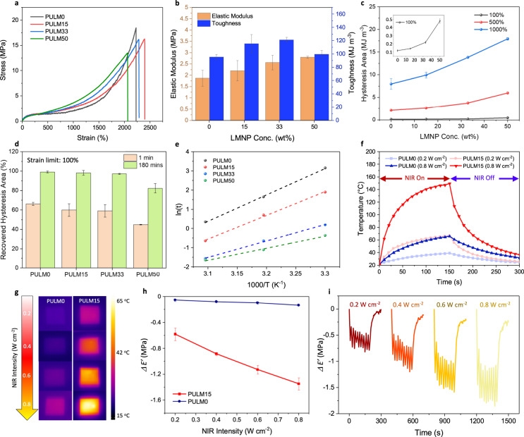
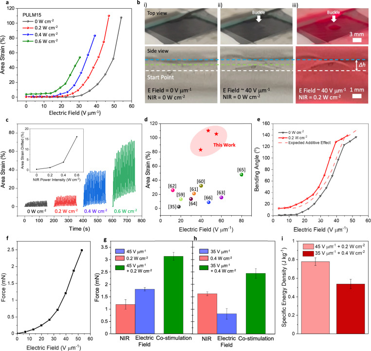
Soft robots need to be resilient to extend their operation under unpredictable environments. While utilizing elastomers that are tough and healable is promising to achieve this, mechanical enhancements often lead to higher stiffness that deteriorates actuation strains. This work introduces liquid metal nanoparticles into carboxyl polyurethane elastomer to sensitize a dielectric elastomer actuator (DEA) with responsiveness to electric fields and NIR light. The nanocomposite can be healed under NIR illumination to retain high toughness (55 MJ m-3) and can be recycled at lower temperatures and shorter durations due to nanoparticle-elastomer interactions that minimize energy barriers. During co-stimulation, photothermal effects modulate the elastomer moduli to lower driving electric fields of DEAs. Bilayer configurations display synergistic actuation under co-stimulation to improve energy densities, and enable a DEA crawler to achieve longer strides. This work paves the way for a generation of soft robots that achieves both resilience and high actuation performance.


Conflict of interest statement

The authors declare no competing interests

Figures

Fig. 1
Fig. 1. Material characterization of LMNPs and PULM nanocomposites.
a Chemical structure of elastomer matrix PULM0. b Digital images of bulk liquid metal with a silver reflective surface and LMNPs that showed a dark gray color after probe sonication and drying. c SEM image of obtained LMNPs. d Size distribution histogram of LMNPs from DLS measurements e Contact angle of bulk liquid metal on PULM0 substrate at 0 min and 480 min. Standard deviation (SD) is obtained from three independent samples. Data is presented in the form of mean values ± SD. f DSC heating curves of LMNPs and PULM nanocomposites at a heating rate of 10 °C/min under a nitrogen atmosphere. g WAXS comparisons of LMNPs and PULM nanocomposites h SAXS comparison between PULM nanocomposites.
Fig. 2
Fig. 2. Mechanical, photothermal and photomechanical properties of PULM nanocomposites.
a Tensile stress strain curve of PULM nanocomposites under a strain rate of 100 mm min−1. b Elastic modulus and mechanical toughness of PULM nanocomposites. c Hysteresis area when PULM nanocomposites are pulled to 100, 500, and 1000% strain after the first cycle of cyclic stress–strain measurements. Inset shows the hysteresis area at 100% strain. d Recovered hysteresis area of PULM nanocomposite cyclic stress–strain curves after a 1 min and 180 min delay at 100% strain. e Arrhenius fittings (dashed lines) of ln(t) versus scaled inverse temperature. t refers to the relaxation time. Slope of Arrhenius fittings represents the relaxation activation energies. f Temperature change profile of PULM0 and PULM15. NIR light was turned on for 150 s at 0.2 W cm−2 or 0.8 W cm−2 and subsequently turned off for films to cool down. g IR images of PULM0 and PULM15 illuminated at different NIR light intensity for 150 s. h Change in storage modulus (ΔE’) of PULM0 and PULM15 after 10 s of NIR light illumination as a function of NIR light intensity. i Change in storage modulus (ΔE’) of PULM15 as a function of time after turning on and off the NIR light for 10 cycles at a frequency of 0.05 Hz followed by cooling for 100 s. All error bars are the standard deviation of three independent samples.
Fig. 3
Fig. 3. Self-healing and recyclability of PULM15 nanocomposite.
a Recovered toughness of PULM15 at different NIR light intensity for 30 min. b Recovered toughness of PULM15 at different healing times under NIR light of 0.2 W cm−2. c Optical microscope images of PULM15 damaged (left, 0 min) and healed after 120 min under NIR light of 0.2 W cm−2. d Digital images of PULM0 and PULM15 waste material before and after hot-pressing for 100 °C for 15 min. PULM0 failed to be recycled while PULM15 was successfully recycled into a film. e Tensile stress strain curve of PULM15 and recycled PULM15 (three cutting-recycling cycle) under a strain rate of 100 mm min−1. All error bars are the standard deviation of three independent samples.
Fig. 4
Fig. 4. Performance of resilient DEAs.
a Dielectric constant and loss of PULM nanocomposites. Error bars are the standard deviation of five independent samples. b Representative area strains achieved by PULM nanocomposite DEAs. Area strains calculated are based on geometric relations from out-of-plane displacements of the buckled electroactive regions. c Representative area strains achieved by PULM15, recycled PULM15 after mechanical damages (cut into pieces) and electrical damage (dielectric breakdown). d Hole observed at the electrode area is attributed to dielectric breakdown. e Optical microscope image of dielectric breakdown site and same site after undergoing the recycling process. f Recycled film after dielectric breakdown can be pulled up to 250% without indicating any holes and damages. g Ashby chart summarizing the healed area strains vs electric fields of various DEA works that can recover its performance after mechanical (solid symbol) or electrical damage (hollow symbol) through self-healing or recycling processes. Actuated radial strains have been approximated to area strains.
Fig. 5
Fig. 5. Co-stimulation of PULM15 DEA.
a Representative area strains of PULM15 DEAs driven by electric field (E field) and NIR light. b Digital images of top and side views of PULM15 DEA in the (i) original state (ii) solely driven by electric field, and (iii) simultaneously driven by electric field and NIR light. Dotted lines indicate the height of out-of-plane displacements during actuation. Δh represents the change in height between the original and co-stimulated state. c Cyclic actuation of PULM15 DEA being simultaneously driven by electric field and NIR light at 0.1 Hz. Inset shows the drifted area strains after 15 cycles as a function of NIR light intensity. d Ashby chart summarizing the area strains vs electric fields of DEAs that utilize fillers. e Representative bending angles of PULM15 DEMES individually driven by electric field and simultaneously driven by electric fields and NIR light intensity of 0.2 W cm−2. Dotted line represents expected additive effects based on the addition of bending angles when driven by electric field and NIR light individually. f Representative blocking force of PULM15 DEMES g Blocking force output of PULM15 DEMES when activated solely by an electric field of 45 V μm−1 (blue) or NIR light intensity of 0.2 W cm−2 (red), and when co-stimulated by both electric field and NIR light (green). h. Blocking force output of PULM15 DEMES when activated solely by an electric field of 35 V μm−1 (blue) or NIR light intensity of 0.4 W cm−2 (red), and when co-stimulated by both electric field and NIR light (green). i Specific energy density of PULM15 DEMES under co-stimulation at various electric fields and NIR light power intensities. All error bars are the standard deviation of three independent samples.
Fig. 6
Fig. 6. Locomotion analysis of DEMES crawler.
a Schematic and digital images of the working principle of two-anchor crawling locomotion of a DEMES crawler. When a voltage (V) is applied, the crawler flattens and extends to give a vertical (Δy) and lateral displacement (Δx). After the voltage is removed, asymmetric friction from the bent front PET leg enables the crawler to crawl forward. b Schematic and digital image of the usage of NIR light as a secondary control to increase the stride of the crawler, with larger Δx and Δy. c Δy and Δx of two-anchor crawling locomotion as a function of time. First, the crawler was driven by an electric field of 35 V μm−1 at 1 Hz. After which, NIR light (0.4 W cm−2) was applied continuously while the crawler was driven by the same electric field. When NIR light was applied, the enhanced stride led to a larger distance traveled. d Digital image of the crawler driven by 35 V μm−1 at 1 Hz to crawl under a low tunnel (width 50 mm × length 5 mm × height 18 mm). When the crawler comes into contact with the tunnel (40 s), it first attempts to adapt its body to crawl under the tunnel based on its soft and flexible nature (40–70 s). Due to the larger height of the crawler, it eventually gets stuck in the tunnel. When NIR light is applied, the crawler is able to release itself to crawl through the tunnel due to a larger vertical displacement generated during crawling.

References

    1. Kim S, Laschi C, Trimmer B. Soft robotics: a bioinspired evolution in robotics. Trends Biotechnol. 2013;31:287–294. - PubMed
    1. Rich SI, Wood RJ, Majidi C. Untethered soft robotics. Nat. Electron. 2018;1:102–112.
    1. Bilodeau RA, Kramer RK. Self-healing and damage resilience for soft robotics: a review. Front. Robot. AI. 2017;4:48.
    1. Terryn S, et al. A review on self-healing polymers for soft robotics. Mater. Today. 2021;47:187–205.
    1. Tan, M. W. M., Thangavel, G. & Lee, P. S. Rugged soft robots using tough, stretchable, and self‐healable adhesive elastomers. Adv Functional Mater.31, 2103097 (2021).