. 2022 Nov 3;13(11):1018.
doi: 10.3390/insects13111018.

Model-Based Tracking of Fruit Flies in Free Flight

Affiliations

Model-Based Tracking of Fruit Flies in Free Flight

Omri Ben-Dov et al. Insects. .

Abstract

Insect flight is a complex interdisciplinary phenomenon. Understanding its multiple aspects, such as flight control, sensory integration, physiology and genetics, often requires the analysis of large amounts of free flight kinematic data. Yet, one of the main bottlenecks in this field is automatically and accurately extracting such data from multi-view videos. Here, we present a model-based method for the pose estimation of free-flying fruit flies from multi-view high-speed videos. To obtain a faithful representation of the fly with minimum free parameters, our method uses a 3D model that includes two new aspects of wing deformation: A non-fixed wing hinge and a twisting wing surface. The method is demonstrated for free and perturbed flight. Our method does not use prior assumptions on the kinematics apart from the continuity of the wing pitch angle. Hence, this method can be readily adjusted for other insect species.

Keywords: drosophila; insect flight; pose estimation; tracking.


Conflict of interest statement

The authors declare no conflict of interest.

Figures

Figure A1
Figure A1
Comparing the 17-DOF model to hull reconstruction tracking in a Cartesian camera configuration. The six plots show 25 ms of wing angles data for both wings, comparing the results of two algorithms: The 17-DOF fitted model reported here (blue) and the hull reconstruction tracking reported in [11,13,14] (red). The video was taken at 8000 frames per second and 512×512 pixel resolution.
Figure A2
Figure A2
Comparing the 17-DOF model to hull reconstruction tracking in the current camera configuration. The unperturbed flight video from Figure 9 was analyzed using a hull reconstruction algorithm which approximates the performance of the methods reported in [13,14] by adjusting the latter method to the current camera configuration, higher resolution and higher frame rate. (a) The elevation angle of the right wing θR as a function of the stroke angle of the same wing ϕR. Results of the 17-DOF model (red) are less noisy and more self-consistent than the results of the hull reconstruction method, especially when the wings are at the back (ϕR=130180°). (b) The reconstructed hull and the fitted 17-DOF model, both superimposed. In this video frame, when the wings are at the back, wing–wing and body–wing occlusions result in a oversized wing hull, which causes errors in the wing pose estimation. For example, both chord vectors are wrongly identified by the hull reconstruction method (red and blue line). In this example, the wings’ DOFs are correctly identified by the 17-DOF model.
Figure 1
Figure 1
Basic 12-DOF model parameters. (a) Body 6 DOF describing its position and orientation. (b) Each wing is described by 3 Euler angles relative to the stroke plane: Stroke (ϕ), elevation (θ) and wing pitch (ψ). The annotations are for the left wing.
Figure 2
Figure 2
Experimental setup. Three orthogonal high-speed cameras focused on a transparent chamber. The non-Cartesian setup reduces wing occlusions.
Figure 3
Figure 3
Pre-processing of free flying videos. (a) Superimposition of 6 raw images mid flight. (b) Background extracted by taking pixel-wise maximum. (c) Subtraction of a single frame from the background. (d) Histogram of subtracted image. The distribution is almost uni-modal. (e) Histogram of subtracted image after power transformation. Distribution is more bi-modal. (f) Resulting mask after applying Otsu’s threshold on transformed difference image.
Figure 4
Figure 4
Wing deformations. (a) Top: Three frames from different phases of a single wing beat. Bottom: Superimposing the 3 frames shows that the wing hinge is effectively not fixed during the stroke. The solid lines marking the leading edge of the wing do not intersect at a single point (dashed lines). (b) An unsuccessful fitting attempt using a rigid wing on a frame with a twisted wing during supination. (c) Wing deformation used in our 3D model. Color represents deformation level, and the black line shows the rigid wing outline. (d) A successful fit using a flexible wing.
Figure 5
Figure 5
Single-frame loss function. XOR operation on the camera image mask (yellow) and the projected model.
Figure 6
Figure 6
Degeneracy in ψ. (a,b) The 3D model generated by two sets of parameters. The orange arrow shows the direction of the camera taking the images on the bottom. (c,d) The projection of the corresponding models on the camera plane. The projections are nearly identical. (e) The loss function (z-axis) at the presented frame by changing only ψ and ϕ (x-axis and y-axis, respectively).
Figure 7
Figure 7
Model validation on synthetic data. Tracking errors box plot. Each box contains 75% of the data. Whiskers correspond to 99.3% of the data.
Figure 8
Figure 8
Naive errors vs. error detection. Each graph is a histogram of the errors for each DOF. The blue bars are the naive optimization process and the orange bars are the process using error detection.
Figure 9
Figure 9
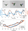
Results on an unperturbed flight event. (a) The projection of a fitted 3D model superimposed on the corresponding frames. (b) Body pitch and wing ϕ. Body pitch oscillations are marked in black vertical arrows. (c) The path of the wing tip by its elevation (θ) and azimuth (ϕ).
Figure 10
Figure 10
Comparison between the 12-DOF and 17-DOF models. The body roll (a) and yaw (b) angles found using the 12-DOF (blue) and 17-DOF (red) models, both for the same unperturbed, non-maneuvering flight data.
Figure 11
Figure 11
Free flight maneuver. (a) Body angles. (b) Wings stroke angles. (c) A drawing of the path and body angles of the fly. The red rods represent the orientation of body at different time points, with the circular end marking the head. The blue rods attached to the red rods represent the wing span vector, visualizing the yaw and roll angles. A small circle on the left marks the start of the video.
Figure 12
Figure 12
Roll correction. (a) Body angles during the maneuver. Magnetic pulse was activated between t=07.5ms. An orange vertical arrow marks the time of maximum angular deflection in roll, yaw and pitch. (b) Wings stroke angles. Blue line and red dashed line mark ϕ and ϕr respectively. The rectangle marks the main wing asymmetry during the maneuver. (c) Top view of the fitted model shows every two wing beats when the left wing is at supination. Wing stroke asymmetry is clearly visible. (d) Flight trajectory and body pose plotted in 1 wingbeat intervals during the maneuver. The body x axis is plotted in red lines, with a red dot indicating the head, and the body y direction is represented by blue line. The trajectory starts at the top corner of the plotted box. A 2D projection of the trajectory is plotted on the xy plane (black line), with the time of the perturbation marked by a thicker line.

References

    1. Dudley R. The Biomechanics of Insect Flight: Form, Function, Evolution. Princeton University Press; Princeton, NJ, USA: 2002.
    1. Dickinson M.H., Muijres F.T. The aerodynamics and control of free flight manoeuvres in Drosophila. Phil. Trans. R. Soc. B. 2016;371:20150388. doi: 10.1098/rstb.2015.0388. - DOI - PMC - PubMed
    1. Floreano D., Wood R.J. Science, technology and the future of small autonomous drones. Nature. 2015;521:460. doi: 10.1038/nature14542. - DOI - PubMed
    1. Fry S.N., Sayaman R., Dickinson M.H. The aerodynamics of hovering flight in Drosophila. J. Exp. Biol. 2005;208:2303–2318. doi: 10.1242/jeb.01612. - DOI - PubMed
    1. Kassner Z., Dafni E., Ribak G. Kinematic compensation for wing loss in flying damselflies. J. Insect Physiol. 2016;85:1–9. doi: 10.1016/j.jinsphys.2015.11.009. - DOI - PubMed

LinkOut - more resources