. 2022 Nov 4;15(21):7794.
doi: 10.3390/ma15217794.

A Gaussian to Vector Vortex Beam Generator with a Programmable State of Polarization

Affiliations

A Gaussian to Vector Vortex Beam Generator with a Programmable State of Polarization

Jacek Piłka et al. Materials (Basel). .

Abstract

We study an optical device designed for converting the polarized Gaussian beam into an optical vortex of tunable polarization. The proposed device comprised a set of three specially prepared nematic liquid crystal cells and a nano-spherical phase plate fabricated from two types of glass nanotubes. This device generates a high-quality optical vortex possessing one of the multiple polarization states from the uniformly polarized input Gaussian beam. Its small size, simplicity of operation, and electrical steering can be easily integrated into the laboratory and industrial systems, making it a promising alternative to passive vortex retarders and spatial light modulators.

Keywords: beam polarization conversion; optical vortices; structured light polarization.


Conflict of interest statement

The authors declare no conflict of interest.

Figures
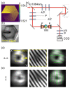
Figure 1
Figure 1
(a) Schematic representation of the vortex nanostructure with 101 rods on the diagonal. Yellow (violet) dots represent high (low) refractive index rods; (b) Photo of the examined structure; (c) Sketch of the experimental setup: VM—vortex mask, F—lens, CCD—digital camera; (d) Experimental results of Gaussian beam transformation through the examined structure. The left, middle, and right panels represent the output intensity distribution, phase singularity within the marked area, and polarization distribution, respectively. Obtained for the wavelength of λ = 1064 nm and linear polarization (horizontal direction—schematically marked by the black arrow); (e) Experimental results of Gaussian beam transformation for a linearly polarized input beam, vertical direction—orthogonal to the input beam in (d).
Figure 2
Figure 2
(a) Schematic representation of the NLC polarization converter composed of three independent NLC cells, controlled by the external voltage; (b) π-phase retarder; (c) waveplate; and (d) θ-plate. Schematic representation of each cell presented in (bd): solid (dotted) black lines indicate the alignment of molecules at the input (output) side, grey areas—ITO layer.
Figure 3
Figure 3
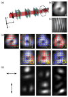
The experimental results of converting the y-polarized Gaussian beam using NLC-PC into (a) uniform and (b) cylindrically symmetric SOP. Blue and red represent right- and left-handedness, respectively, and yellow arrows show the desired output SOP achieved by applying proper U1, U2, and U3 voltages, as summarized in Table 1.
Figure 4
Figure 4
(a) Schematic representation of Gaussian-vortex polarization converter consisting of NLC-PC and VM; The result of linearly polarized Gaussian beam transformation into an optical vortex: (b) doughnut-shaped intensity profile of a linear (horizontal) output polarization, (c) fork-like interference fringes; (d) the result of the polarization conversion of the vortex beam into seven different SOPs (from the left-top panel): linear horizontal, linear vertical, circular right- and left-handed, azimuthal, radial, and vortical; (e) horizontal (top panels) and vertical (bottom panels) linear polarization components (schematically marked by the black arrows) of azimuthal, radial, and vortical SOPs.
Figure 5
Figure 5
The intensity and polarization distribution of generated vector vortex beams that result from the conversion of (ad) linear (vertical) polarized Gaussian input beam; (eh) left-handed circular polarized input Gaussian beam for U1 = 0 V, U3 = 5 V driving voltages, and for the following U2 voltages: (a) U2 = 2.2 V; (b) U2 = 1.3 V; (c) U2 = 1.6 V; (d) U2 = 3.3 V; (e) U2 = 3.3 V; (f) U2 = 1.6 V; (g) U2 = 2.2 V; (h) U2 = 1.3 V.

References

    1. Rubinsztein-Dunlop H., Forbes A., Berry M.V., Dennis M.R., Andrews D.L., Mansuripur M., Denz C., Alpmann C., Banzer P., Bauer T., et al. Roadmap on Structured Light. J. Opt. 2017;19:013001. doi: 10.1088/2040-8978/19/1/013001. - DOI
    1. Yao A.M., Padgett M.J. Orbital Angular Momentum: Origins, Behavior and Applications. Adv. Opt. Photon. AOP. 2011;3:161–204. doi: 10.1364/AOP.3.000161. - DOI
    1. Soskin M., Vasnetsov M. Chapter 4—Singular Optics. Prog. Opt. 2001;42:219–276. doi: 10.1016/S0079-6638(01)80018-4. - DOI
    1. Zhan Q. Cylindrical Vector Beams: From Mathematical Concepts to Applications. Adv. Opt. Photon. AOP. 2009;1:1–57. doi: 10.1364/AOP.1.000001. - DOI
    1. Brown T.G. Progress in Optics. Volume 56. Elsevier; Amsterdam, The Netherlands: 2011. Unconventional polarization states: Beam propagation, focusing, and imaging; pp. 81–129. - DOI

LinkOut - more resources