

3D Metrology Using One Camera with Rotating Anamorphic Lenses
- PMID: 36366104
- PMCID: PMC9656777
- DOI: 10.3390/s22218407
3D Metrology Using One Camera with Rotating Anamorphic Lenses
Abstract
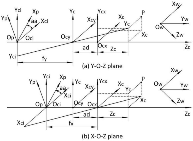
In this paper, a novel 3D metrology method using one camera with rotating anamorphic lenses is presented based on the characteristics of double optical centers for anamorphic imaging. When the anamorphic lens rotates -90° around its optical axis, the 3D data of the measured object can be reconstructed from the two anamorphic images captured before and after the anamorphic rotation. The anamorphic lens imaging model and a polynomial anamorphic distortion model are firstly proposed. Then, a 3D reconstruction model using one camera with rotating anamorphic lenses is presented. Experiments were carried out to validate the proposed method and evaluate its measurement accuracy. Compared with stereo vision, the main advantage of the proposed 3D metrology approach is the simplicity of point matching, which makes it suitable for developing compact sensors for fast 3D measurements, such as car navigation applications.
Keywords: 3D reconstruction; anamorphic lens; anamorphic stereo vision.
Conflict of interest statement
The authors declare no conflict of interest.
Figures


Similar articles
-
High-precision anamorphic lens calibration with 3D and 2D calibration targets.Appl Opt. 2022 Jul 10;61(20):6062-6075. doi: 10.1364/AO.456166. Appl Opt. 2022. PMID: 36255848
-
Camera calibration for anamorphic lenses with three-dimensional targets.Appl Opt. 2020 Jan 10;59(2):324-332. doi: 10.1364/AO.59.000324. Appl Opt. 2020. PMID: 32225310
-
Anamorphic zoom lens based on rotating cylindrical lenses.Opt Express. 2021 Apr 12;29(8):12206-12214. doi: 10.1364/OE.422097. Opt Express. 2021. PMID: 33984985
-
On-line three-dimensional coordinate measurement of dynamic binocular stereo vision based on rotating camera in large FOV.Opt Express. 2021 Feb 15;29(4):4986-5005. doi: 10.1364/OE.414365. Opt Express. 2021. PMID: 33726043
-
Paraxial lens design of double-telecentric anamorphic zoom lenses with variable magnifications or fixed conjugate.J Opt Soc Am A Opt Image Sci Vis. 2019 Dec 1;36(12):1977-1990. doi: 10.1364/JOSAA.36.001977. J Opt Soc Am A Opt Image Sci Vis. 2019. PMID: 31873368
References
-
- Leach R. Optical Measurement of Surface Topography. China Science Publishing & Media Ltd.; Beijing, China: 2012. pp. 154–196.
-
- Gaha R., Durupt A., Eynard B. Towards the implementation of the Digital Twin in CMM inspection process: Opportunities, challenges and proposals. Procedia Manuf. 2021;54:216–221. doi: 10.1016/j.promfg.2021.07.033. - DOI
-
- Sutton M.A., Li N., Joy D.C., Reynolds A.P., Li X. Scanning electron microscopy for quantitative small and large deformation measurements part I: SEM imaging at magnifications from 200 to 10,000. Exp. Mech. 2007;47:775–787. doi: 10.1007/s11340-007-9042-z. - DOI
-
- Harding K. Challenges and opportunities for 3D optical metrology: What is needed today from an industry perspective. Two-Three-Dimens. Methods Insp. Metrol. VI. 2008;7066:112–119.
Grants and funding
LinkOut - more resources
Full Text Sources
