. 2022 Nov 11;8(45):eabo0869.
doi: 10.1126/sciadv.abo0869. Epub 2022 Nov 11.

3D stretchable and self-encapsulated multimaterial triboelectric fibers

Affiliations

3D stretchable and self-encapsulated multimaterial triboelectric fibers

Chaoqun Dong et al. Sci Adv. .

Abstract

A robust power device for wearable technologies and soft electronics must feature good encapsulation, high deformability, and reliable electrical outputs. Despite substantial progress in materials and architectures for two-dimensional (2D) planar power configurations, fiber-based systems remain limited to relatively simple configurations and low performance due to challenges in processing methods. Here, we extend complex 2D triboelectric nanogenerator configurations to 3D fiber formats based on scalable thermal processing of water-resistant thermoplastic elastomers and composites. We perform mechanical analysis using finite element modeling to understand the fiber's deformation and the level of control and engineering on its mechanical behavior and thus to guide its dimensional designs for enhanced electrical performance. With microtexture patterned functional surfaces, the resulting fibers can reliably produce state-of-the-art electrical outputs from various mechanical deformations, even under harsh conditions. These mechanical and electrical attributes allow their integration with large and stretchable surfaces for electricity generation of hundreds of microamperes.


Figures

Fig. 1.
Fig. 1.. Fabrication and structure of the stretchable, self-encapsulated fiber power system.
(A) Schematic showing the thermal processing of a multimaterial preform into long fibers. (B) The preparation procedures of microtextured thermoplastic elastomers from a patterned mask. (C) Schematic showing the detailed structure and fabrication of the preform. The zoom-in illustration highlights the microtextured surfaces. (D) Photograph of a continuous 10-m-long fiber, showing the scalability of the fabrication process. (E to G) Scanning electron microscopy (SEM) images of fiber cross sections with microtextured inner surfaces. All necessary functional materials for electricity generation are fully encapsulated within a soft SEBS cladding. (H) Photographs of a 10-cm-long fiber being twisted or stretched to 100% strain with intact structure and consistent electrical conductivity, as indicated by the same brightness of a connected light-emitting diode (LED) that is powered through the two electrodes of the fiber.
Fig. 2.
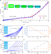
Fig. 2.. FEM of the deformation of the fiber cross section.
(A) Comparison of the mechanical response of the compressed fiber structure obtained through experimentation and FEM: pressure versus displacement. Insets present the simulated maximum principal logarithmic strain distributed in the fiber cross section during compression. The corresponding pressures and compressive displacements are indicated in the loading curve labeled by red dots. (B to E) Effects of variations of the width and height of the open channel on the mechanical behavior of the fiber. (B and D) Loading curves for fibers with varied width [in (B), x1/x0 ranging from 0.5 to 0.95, y1/y0 = 0.23] or height [in (D), y1/y0 between 0.05 and 0.35, x1/x0 = 0.8]. Note that the other dimensions are fixed and identical to those of the fiber sample tested in the experiment shown in (A). (C and E) Extracted values of pressure and compressive displacement as the top and bottom surfaces surrounding the channel come into contact. Schematics of initial fiber configurations with varying x1/x0 and y1/y0 are shown in the insets of (B) and (D), respectively.
Fig. 3.
Fig. 3.. Materials selection and characterization.
(A) A water drop on a SEBS film showing the contact angle of approximately 104.4°. (B) The logarithm of WVTR values of SEBS as a function of the reciprocal of absolute temperatures (1/T) for the extraction of its permeation activation energy. (C and D) SEM images of the stretchable and conductive composite film, indicating the distribution and dimensions of the CNT fillers. (E) Stress-strain curves of the conductive composite before thermal drawing. (F) Measurement of the resistance versus length showing their linear relationship results from the overall homogeneous distribution of CNTs. (G) Surface tension studies of the involved polymers in this work. The data are extracted from a series of contact angle measurements. (H) Stress-strain curves of the energy harvesting fiber devices. (I) Dynamic mechanical tensile test of a fiber being stretched over 200 cycles under the applied forces in the range of 0.1 to 1.1 N.
Fig. 4.
Fig. 4.. Electrical characterization of the triboelectric fibers.
(A) Numerical calculations of the potential distributions at different distances (x) between the two triboelectric surfaces and calculated voltages versus x. (B) Relationship between ∆Q/Q0 and x. (C) Electrical responses of the microtextured fibers under pressing with different frequencies. The fiber is 2.3 mm in width, 1.4 mm in thickness, and 3 cm in effective length. (D) Compressing pressure versus displacement. (E) Dependence of ISC on compressing pressure. The shaded region highlights the pressures of 110 to 140 kPa that are high enough to trigger the gradual contact of the triboelectric surfaces. (F and G) The output as the fiber is connected to various resistors. (H) Long-term output stability under continuous pressing for 70,000 cycles. (I) Comparison of the fiber’s output before and after being immersed in water for 1 and 2 days. The fiber was tested directly without further drying after being taken out from water. (J) Schematic showing the sample preparation for in situ SEM characterization. (K) In situ SEM images of a fiber with 0 and 67% elongation strain. (L) VOC of the fiber under various repeated stretching and release movements. Inset shows the effects of mechanical stretching to the electric potential distribution.
Fig. 5.
Fig. 5.. Electrical output characterizations of long fibers.
(A) Photograph of a continuous 10-m-long triboelectric fiber is integrated in a serpentine pattern on the surface of a stretchable fabric. The right schematic indicates the triggering mode for (B) and (C). (B and C) Open-circuit voltage of the long stretchable fiber triggered by a stretch along the longitudinal direction of the fabric and compressions at different positions. (D to F) Electrical outputs of the long fiber triggered by hand compression with increased foce (D), free fall of blocks with varied weights and surface areas (E), and jumping of a male researcher in our group (F).

References

    1. Hashemi S. A., Ramakrishna S., Aberle A. G., Recent progress in flexible-wearable solar cells for self-powered electronic devices. Energ. Environ. Sci. 13, 685–743 (2020).
    1. Kim B. J., Kim D. H., Lee Y. Y., Shin H. W., Han G. S., Hong J. S., Mahmood K., Ahn T. K., Joo Y. C., Hong K. S., Park N. G., Lee S., Jung H. S., Highly efficient and bending durable perovskite solar cells: Toward a wearable power source. Energ. Environ. Sci. 8, 916–921 (2015).
    1. Pan S., Yang Z., Chen P., Deng J., Li H., Peng H., Wearable solar cells by stacking textile electrodes. Angew. Chem. 126, 6224–6228 (2014). - PubMed
    1. Allison L. K., Andrew T. L., A wearable all-fabric thermoelectric generator. Adv Mater Technol. 4, 1800615 (2019).
    1. Kim S. J., We J. H., Cho B. J., A wearable thermoelectric generator fabricated on a glass fabric. Energ. Environ. Sci. 7, 1959–1965 (2014).