. 2022 Nov 7:16:1018160.
doi: 10.3389/fnhum.2022.1018160. eCollection 2022.

Bio-inspired design of a self-aligning, lightweight, and highly-compliant cable-driven knee exoskeleton

Affiliations

Bio-inspired design of a self-aligning, lightweight, and highly-compliant cable-driven knee exoskeleton

Shuangyue Yu et al. Front Hum Neurosci. .

Abstract

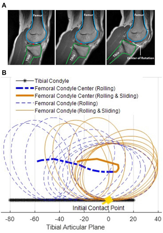
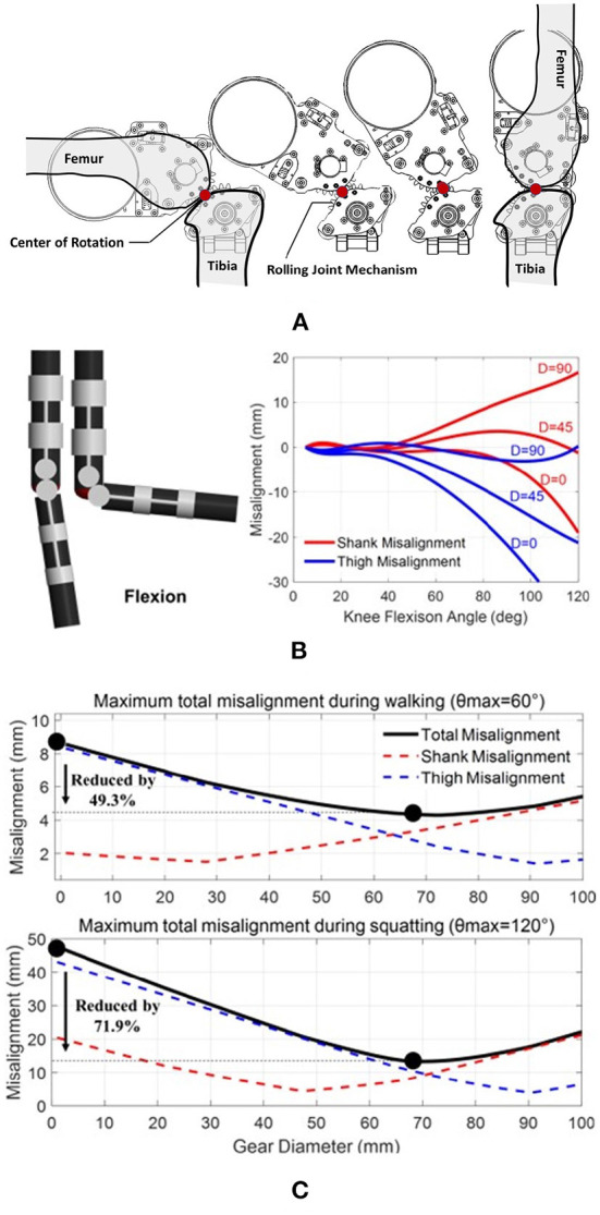
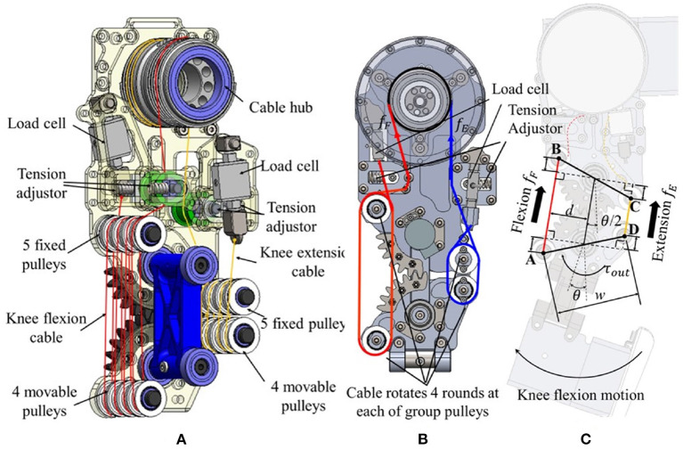
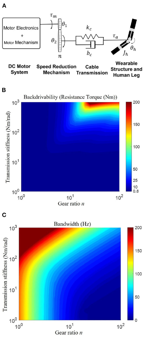
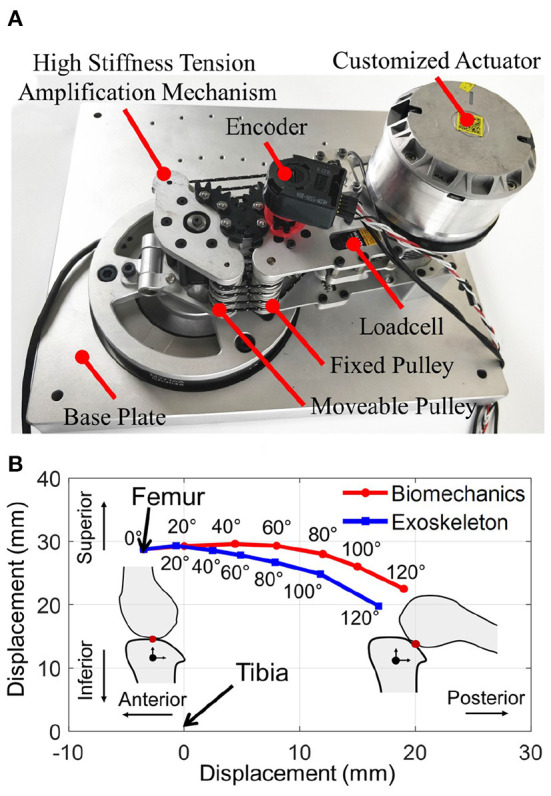
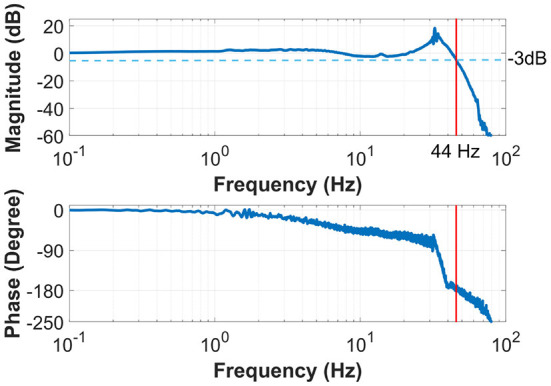
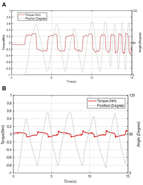
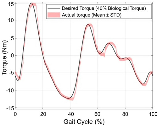
Powered knee exoskeletons have shown potential for mobility restoration and power augmentation. However, the benefits of exoskeletons are partially offset by some design challenges that still limit their positive effects on people. Among them, joint misalignment is a critical aspect mostly because the human knee joint movement is not a fixed-axis rotation. In addition, remarkable mass and stiffness are also limitations. Aiming to minimize joint misalignment, this paper proposes a bio-inspired knee exoskeleton with a joint design that mimics the human knee joint. Moreover, to accomplish a lightweight and high compliance design, a high stiffness cable-tension amplification mechanism is leveraged. Simulation results indicate our design can reduce 49.3 and 71.9% maximum total misalignment for walking and deep squatting activities, respectively. Experiments indicate that the exoskeleton has high compliance (0.4 and 0.1 Nm backdrive torque under unpowered and zero-torque modes, respectively), high control bandwidth (44 Hz), and high control accuracy (1.1 Nm root mean square tracking error, corresponding to 7.3% of the peak torque). This work demonstrates performance improvement compared with state-of-the-art exoskeletons.

Keywords: bioinspired design; cable-driven; complaint actuators; knee exoskeleton; self-alignment.


Conflict of interest statement

The authors declare that the research was conducted in the absence of any commercial or financial relationships that could be construed as a potential conflict of interest.

Figures

Figure 1
Figure 1
The bio-inspired design of a lightweight cable-driven knee exoskeleton aims to reduce negative design effects in terms of joint misalignment mitigation, lightweight, and high compliance. (A) Side view in a standing position. (B) Crouched down posture that demonstrates the wide range of motion of the device, being not restrictive of the wearer's free movements.
Figure 2
Figure 2
(A) Magnetic resonance imaging (MRI) scanned for human knee joint when the knee joint is moving from extension (left) to flexion (right). The blue and green contours indicate the femur and the tibia, respectively. The red dot represents the knee joint center of rotation. (B) Simulation result of femoral condyle center during −5° to 120° knee flexion movement using both pure rolling model (dotted blue lines) and rolling-sliding combined model (solid orange lines). Compared with the pure rolling femoral condyle center trajectory (bold dashed blue line), the rolling and sliding joint condyle center trajectory (bold solid orange line) allows the center of the femoral condyle to have smaller locomotion at the tibial articular plane with respect to the tibia (black line). The result indicates a non-fixed axis robot knee joint can mitigate misalignment compared with a traditional axis fixed robot knee rolling joint.
Figure 3
Figure 3
(A) The bioinspired rolling-gear based knee joint mechanism can provide equivalent rolling and sliding motion during knee joint movement. Compared with traditional fix-axis rotation robot joint designs, the design can mitigate joint misalignment. The non-fixed rotation center is defined by the contact point between the two gears; (B) Simulation of the misalignment effect for the rolling joint design. The red and the blue lines represent the misalignment functions at the shank and the thigh during the knee flexion motion, respectively; (C) Joint misalignment reduction simulation results during walking (θmax = 60°) and deep squatting (θmax = 120°).
Figure 4
Figure 4
The detailed structure of the knee exoskeleton. (A) The flexion cable (red line) and extension cable (yellow line) is driven by a cable hub and pass through fixed (upper) and movable (lower) pulleys used to realize the tension-amplification mechanism. (B) Cable routing, force sensing, and tension adjuster. (C) Relationship between the cable motion and joint angle. High stiffness cable-tension amplification mechanism. The tension-amplification mechanism realizes the function of the speed reduction mechanism with a gear ratio of 8 and the resultant stiffness is 64 times the stiffness of the cable, see Equation (8).
Figure 5
Figure 5
(A) The framework of the human-exoskeleton interaction model. This model consists of four modules: motor system, speed reduction mechanism, cable transmission, and wearable structures attached to the human. θ1 and θ2 denote the rotation angles of the input gear and output gear, respectively. n, speed reduction ratio; kc, transmission stiffness; bc, transmission damping; Jh, joint inertia of the shank orthosis and human shank; θh, knee angle; τm, motor torque; τa, exoskeleton actual torque. (B,C) Influence of gear ratio and transmission stiffness on backdrivability and control bandwidth. (B) Illustrates the high backdrivability is ensured by either high transmission stiffness or small gear ratio; (C) Shows the high bandwidth requires both high transmission stiffness and small gear ratio. Therefore, both a high transmission stiffness and a small gear ratio are necessary to ensure high backdrivability and high bandwidth.
Figure 6
Figure 6
(A) Overview and exploded view of the custom-designed fully-integrated, lightweight, direct-drive actuator used in the design of the knee exoskeleton (B).
Figure 7
Figure 7
Block diagram of the control architecture. The motor low-level controller performs current PI control by using actuator integrated sensors for feedback, while the high-level torque PID control uses two force sensors to obtain joint torque feedback.
Figure 8
Figure 8
(A) Bench test platform that fixes the thigh and shank links of the joint mechanism; (B) The knee center of rotation displacement result shows our proposed rolling gear based knee joint can reduce joint misalignment and biomimic the rotation trajectory of the biomechanics of the human knee joint.
Figure 9
Figure 9
The Bode plot of the system shows a torque control bandwidth of 44 Hz, much higher than the frequency required for human walking.
Figure 10
Figure 10
Backdrivability performance of the knee exoskeleton in unpowered mode (A) and zero-torque control mode (B).
Figure 11
Figure 11
Tracking torque performance of the 16 Nm peak torque, which is about 40% knee torque assistance required during human walking.

References

    1. Awad L. N., Bae J., O'donnell K., De Rossi S. M., Hendron K., Sloot L. H., et al. . (2017). A soft robotic exosuit improves walking in patients after stroke. Sci. Transl. Med. 9, eaai9084. 10.1126/scitranslmed.aai9084 - DOI - PubMed
    1. Bulea T. C., Sharma N., Sikdar S., Su H. (2022). Next generation user-adaptive wearable robots. Front. Robot. AI 9, 920655. 10.3389/frobt.2022.920655 - DOI - PMC - PubMed
    1. Carrozza M. C., Micera S., Pons J. L. (2018). Wearable robotics: challenges and trends, in Proceedings of the 4th International Symposium on Wearable Robotics, WEROB2018 (Pisa: ). 10.1007/978-3-030-01887-0 - DOI
    1. Celebi B., Yalcin M., Patoglu V. (2013). Assiston-knee: a self-aligning knee exoskeleton, in 2013 IEEE/RSJ International Conference on Intelligent Robots and Systems (Tokyo: IEEE; ), 996–1002. 10.1109/IROS.2013.6696472 - DOI
    1. Chang S.-H., Tseng S.-C., Su H., Francisco G. E. (2022). How can wearable robotic and sensor technology advance neurorehabilitation? Front. Neurorobot. 217, 1033516. 10.3389/fnbot.2022.1033516 - DOI - PMC - PubMed

LinkOut - more resources