Review
. 2022 Nov 18;27(22):8025.
doi: 10.3390/molecules27228025.

Recent Development of Tunable Optical Devices Based on Liquid

Affiliations
Review

Recent Development of Tunable Optical Devices Based on Liquid

Qi Wu et al. Molecules. .

Abstract

Liquid opens up a new stage of device tunability and gradually replaced solid-state devices and mechanical tuning. It optimizes the control method and improves the dynamic range of many optical devices, exhibiting several attractive features, such as rapid prototyping, miniaturization, easy integration and low power consumption. The advantage makes optical devices widely used in imaging, optical control, telecommunications, autopilot and lab-on-a-chip. Here, we review the tunable liquid devices, including isotropic liquid and anisotropic liquid crystal devices. Due to the unique characteristics of the two types of liquids, the tuning principles and tuning methods are distinguished and demonstrated in detail firstly and then some recent progress in this field, covering the adaptive lens, beam controller, beam filter, bending waveguide, iris, resonator and display devices. Finally, the limitations and future perspectives of the current liquid devices are discussed.

Keywords: adaptive liquid lens; beam steering; design; liquid; liquid crystal; optical device; optical filter; tunable.


Conflict of interest statement

The authors declare no conflicts of interest.

Figures

Figure 1
Figure 1
A brief introduction of the tunable liquid devices’ (a) working principle and (b) a diagram that presents the common and unique device type.
Figure 2
Figure 2
Electrical control diagrams of (a) electrowetting when the voltage is off (b) and the voltage is on [40]. (c) The diagrams of dielectrophoresis [41]. Reprinted with permission from Refs. [40,41]. 2004 AIP Publishing and 2013 Elsevier Science.
Figure 3
Figure 3
Simulated refractive index profile due to the diffusion [42]. (a) Simulated model and distribution graph. (b) Cross-sectional refractive index distribution at different locations along the flow direction (1, 2, 3, 4 and 5, as indicated in (a)). Reprinted with permission from Ref. [42]. 2009 Royal Society of Chemistry.
Figure 4
Figure 4
NLC spatially expanded phase distribution. (a) Schematic diagram of the structure of the proposed LC lens. (b) The upper LC refractive index varies with the radius. (c) Lower LC refractive index as a function of radius. (d) Sum of the refractive indices of the upper and lower layers [47]. Reprinted with permission from Ref. [47]. 2019 The Optical Society.
Figure 5
Figure 5
Dual-aperture LC lens at different working states: (a) when the voltage is on and (b) the voltage is off [49]. Reprinted with permission from Ref. [49]. 2022 Elsevier.
Figure 6
Figure 6
LC lens arrays with different layers: (a) resistive layer [27], (b) low dielectric layer [50] and (c) composited dielectric layer [51]. Reprinted with permission from Refs. [27,50,51]. 2020 Taylor & Francis.
Figure 7
Figure 7
Polarizer-free LC micro-lens. (a) Schematic configuration (aperture of a micro-lens: 100 μm). (b) The illustration of a scratched PI area in (a) [53]. Reprinted with permission from Ref. [53]. 2021 The Optical Society.
Figure 8
Figure 8
Schematic depiction of the (a) voltage-dividing electrode. (b) Rectangular transmission line. (c) Triangular transmission line [56]. Reprinted with permission from Ref. [56]. 2020 Springer Nature.
Figure 9
Figure 9
Pattern electrodes with parallel sub-electrodes. (a) Two electrode structures perpendicularly arranged, corresponding to the top and bottom substrates of a LC-cell [57]. (b) Resistance line distribution with a linear function of the coefficient k [63]. Reprinted with permission from Refs. [57,63]. 2020 Springer Nature and 2022 IEEE.
Figure 10
Figure 10
Schematic diagram of (a) LC filter based on a Lyot filter [69] and (b) the wedge CLC cell with a pitch gradient [70]. Reprinted with permission from Refs. [69,70]. 2016 The Optical Society and 2019 IEEE.
Figure 11
Figure 11
The model of the three-dimensional twist sphere structure in the sphere phase [71]. Reprinted with permission from Ref. [71]. 2019 MDPI.
Figure 12
Figure 12
Three-dimensional and cross-section view for a single tunable PD [72]. Reprinted with permission from Ref. [72]. 2018 The Optical Society.
Figure 13
Figure 13
Metamaterial absorber in the THz range: (a) Planar Square Titanium SRR [74]. (b) The decomposition diagram of the LC-integrated dielectric metamaterial [76]. (c) The unit dimension of the pillar resonator: lattice periodicity, p: 210 μm; radius, r: 64 μm; height, h: 60 μm. Reprinted with permission from Refs. [74,76]. 2019 Taylor & Francis and 2018 MDPI.
Figure 14
Figure 14
Dimensions of SRRs with different units: (a) split ring [73] and (b) split square [79]. Reprinted with permission from Refs. [73,79]. 2021 MDPI.
Figure 15
Figure 15
Schematic diagram of a metamaterial absorber based on liquid crystals [80]: (a) top view and (b) side view. Reprinted with permission from Ref. [80]. 2018 MDPI.
Figure 16
Figure 16
Double-layer twisted Bragg grating [84]. Reprinted with permission from Ref. [84]. 2018 Spring Nature.
Figure 17
Figure 17
Schematic illustrations of the PVG structure and stretching process of PVG from an unstrained state to strained state. (a) PVG on PDMS without strain. (b) Strained PVG structure [90]. (c) Three-layer twisted structure PB phase control beam deflector [85]. Reprinted with permission from Refs. [90,85]. 2019 The Optical Society.
Figure 18
Figure 18
Cross-type programmable element grating. (a) Brief circuit schematic diagram. (b) Specific unit allocation control [29].
Figure 19
Figure 19
The elements of the array-grating: (a) square SRR [86] and (b) arc SRR [89]. Reprinted with permission from Refs. [86,89]. 2022 American Chemical Society and 2021 John Wiley and Sons.
Figure 20
Figure 20
Schematic diagram of the structure. Basic structure of the tunable LC-VSCEL the same as the HCG liquid crystal laser control structure are displayed [101]. Reprinted with permission from Ref. [101]. 2022 The Optical Society.
Figure 21
Figure 21
Optical switch structure: (a) nanometal structure [92] and (b) MMI channel switching control [93]. Reprinted with permission from Refs. [92,93]. 2017 Elsevier and 2019 Beilstein-Institut.
Figure 22
Figure 22
Joint control lens of electrowetting and Maxwell force. Schematic of the device consisting of three electrodes (1), (2), (3) with different voltages applied. [123]. Reprinted with permission from Ref. [123]. 2019 The Optical Society.
Figure 23
Figure 23
Multifunctional lens with single- and multi-electrode controls [127]. Reprinted with permission from Ref. [127]. 2020 The Optical Society.
Figure 24
Figure 24
Schematics of the electrical setup to actuate the liquid–liquid interface by EWOD [128]. Reprinted with permission from Ref. [128]. 2019 Spring Nature.
Figure 25
Figure 25
Schematic design of the DEP lens, the DEP force drives the liquid–air interface from concave to convex through: (a) one side [129] and (b) both sides [130]. Reprinted with permission from Refs. [129,130]. 2018 The Optical Society and 2018 Royal Society of Chemistry.
Figure 26
Figure 26
Schematic design of the DEP-actuated aspherical lens with two arrays of ITO electrode strips patterned on the top plate. (a) Working principle of the control of longitudinal spherical aberration (LSA). (b) The lens interfaces are divided into discrete slices with variable local curvatures to form an aspherical lens. (c) Schematic design of the DEP-actuated aspherical lens [131]. Reprinted with permission from Ref. [131]. 2020 Royal Society of Chemistry.
Figure 27
Figure 27
Dual-chamber sandwich DE lens: (a) In the initial state, the three membranes deform due to the hydraulic pressure. (b) Three membranes reshaped when a driving voltage is applied to the copper foil [116]. Reprinted with permission from Ref. [116]. 2020 The Optical Society.
Figure 28
Figure 28
Thermal effect lens actuated by laser-induced: (a) Marangoni forces [133], the laser power axis shows the power increase; (b) solutocapillary forces [134], schema of the droplet formation process by laser, which contributes to the surface tension gradient. Reprinted with permission from Refs. [133,134]. 2018 AIP Pulishing and 2017 Elsevier.
Figure 29
Figure 29
Multichannel mixing GRIN lens. (a) The structure to form the refractive index distribution, and (b) the equivalent optical path diagram of the graded refractive index lens [135]. Reprinted with permission from Ref. [135]. 2016 Royal Society of Chemistry.
Figure 30
Figure 30
Laser-induced thermal gradient. (a) Schematic diagram of the thermal lens, and (b) the simulated two-dimensional refractive index profiles [136]. Reprinted with permission from Ref. [136]. 2016 Royal Society of Chemistry.
Figure 31
Figure 31
The schematic design of fluidic thermal GRIN lens for cell manipulation: The system includes a lens chamber and a cell trapping chamber. Five streams at different temperatures are injected into the microfluidic chip to form a gradient refractive index across the channel [137]. Reprinted with permission from Ref. [137]. 2017 Royal Society of Chemistry.
Figure 32
Figure 32
Diffusion device: (a) Counterflow convection–diffusion, Refractive index profile in a concentration gradient light-bending device [43]. (b) thermal-gradient bending device, conceptual design of the concentration gradient bending device and refractive index profile in a thermal gradient light-bending device [44]. Reprinted with permission from Refs. [43,44]. 2017 and 2020 The Optical Society.
Figure 33
Figure 33
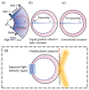
Schematic of a liquid–diffusion optofluidic gradient index resonator. (a) The optofluidic diffusing structure, (b) ray trajectory squeezed and (c) ray trajectories are symmetrical in a conventional circular cavity. (d) Squeezing the light intensity profile enables unidirectional emissions on the low refractive index side [138]. Reprinted with permission from Ref. [138]. 2020 Royal Society of Chemistry.
Figure 34
Figure 34
Schematic diagram of the working mechanism. (a) The thermocapillary flow rises in the upper layer. (b) The thermocapillary deformation of the upper layer and the convex deformation of the bottom layer. (c) The upper thermocapillary rupture [139]. Reprinted with permission from Ref. [139]. 2019 AIP Publishing.
Figure 35
Figure 35
Phase modulator structure. (a) Cross-sectional view of the liquid phase modulator; the bottom electrode configuration: (b) key type; (c) interdigital type. Reprinted/adapted with permission from Ref. [142]. 2021 American Chemical Society.

Similar articles

Cited by

References

    1. Mutailipu M., Pan S. Emergent Deep-Ultraviolet Nonlinear Optical Candidates. Angew. Chem. Int. Ed. 2020;59:20302–20317. doi: 10.1002/anie.201913974. - DOI - PubMed
    1. Mutailipu M., Poeppelmeier K.R., Pan S. Borates: A Rich Source for Optical Materials. Chem. Rev. 2021;121:1130–1202. doi: 10.1021/acs.chemrev.0c00796. - DOI - PubMed
    1. Xu S., Ren H., Wu S.-T. Dielectrophoretically Tunable Optofluidic Devices. J. Phys. D Appl. Phys. 2013;46:483001. doi: 10.1088/0022-3727/46/48/483001. - DOI
    1. Oladepo S.A. Development and Application of Liquid Crystals as Stimuli-Responsive Sensors. Molecules. 2022;27:1453. doi: 10.3390/molecules27041453. - DOI - PMC - PubMed
    1. Wang Z., Zhang Y., Gong X., Yuan Z., Feng S., Xu T., Liu T., Chen Y.-C. Bio-Electrostatic Sensitive Droplet Lasers for Molecular Detection. Nanoscale Adv. 2020;2:2713–2719. doi: 10.1039/D0NA00107D. - DOI - PMC - PubMed

LinkOut - more resources