Review
. 2022 Nov 9;25(12):105518.
doi: 10.1016/j.isci.2022.105518. eCollection 2022 Dec 22.

Microdevice-based mechanical compression on living cells

Affiliations
Review

Microdevice-based mechanical compression on living cells

Sevgi Onal et al. iScience. .

Abstract

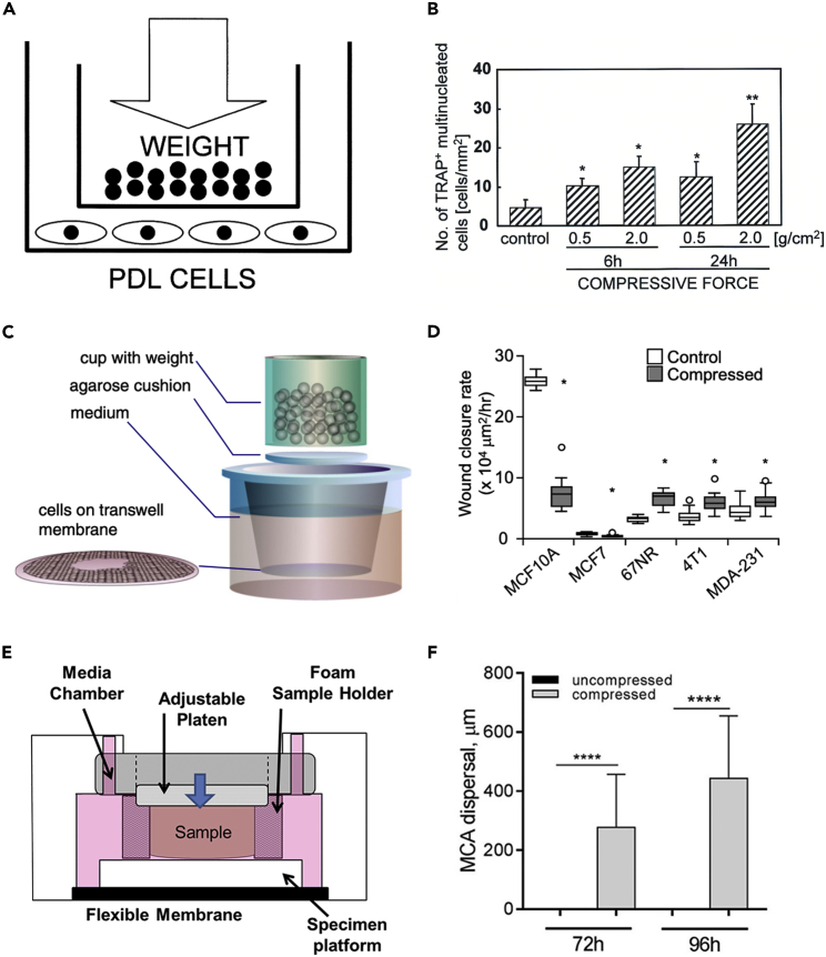
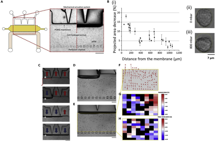
Compressive stress enables the investigation of a range of cellular processes in which forces play an important role, such as cell growth, differentiation, migration, and invasion. Such solid stress can be introduced externally to study cell response and to mechanically induce changes in cell morphology and behavior by static or dynamic compression. Microfluidics is a useful tool for this, allowing one to mimic in vivo microenvironments in on-chip culture systems where force application can be controlled spatially and temporally. Here, we review the mechanical compression applications on cells with a broad focus on studies using microtechnologies and microdevices to apply cell compression, in comparison to off-chip bulk systems. Due to their unique features, microfluidic systems developed to apply compressive forces on single cells, in 2D and 3D culture models, and compression in cancer microenvironments are emphasized. Research efforts in this field can help the development of mechanoceuticals in the future.

Keywords: Mechanobiology; biological sciences; biophysics; cell biology.


Conflict of interest statement

The authors declare no competing interests.

Figures

None
Graphical abstract
Figure 1
Figure 1
Cell compression in bulk platforms (A) Uniform compression method via glass cylinder used to apply compression to periodontal ligament (PDL) cells. Force was controlled by the number of lead granules placed in the cylinder. (B) After compression for an indicated force and time, glass cylinder, weight, and culture medium were removed. Compressed PDL cells were then cultured with peripheral blood mononuclear cells (PBMCs). An increase in the tartrate-resistant acid phosphatase-positive (TRAP+) multinucleated cells indicated up-regulated osteoclastogenesis from PBMCs by mechanical stress. (C) Schematic of in vitro compression device to apply constant compressive forces on a mammary carcinoma cell monolayer via a cup with adjustable weight and monitor cell migration on a transwell membrane. Cell migration under compression was assessed by monitoring the closure of a wound of around 1 mm in diameter scraped at the center. (D) Wound closure rate for five different mammary epithelial cells of increasing invasion potential, with comparison between the corresponding stress-free (control) and the cells subjected to a compressive stress of 5.8 mmHg for 16 h in each group, indicating that compression-induced mammary carcinoma cell migration. (E) BioPress compression well plate and Flexcell Compression Plus System for applying compressive stress to hydrogel/multicellular aggregates (MCAs). (F) Quantitation of OvCa433 MCA dispersal at 72 and 96 h of culture after compression. Reproduced, with permission, from for (A) and (B); from for (C) and (D); from for (E) and (F).
Figure 2
Figure 2
Examples of on-chip compression of cells within 3D hydrogel constructs (A) Design and working principle of gradient strain hydrogels in a microfluidic chip, called GSS-micro-Chip, showing concentric hydrogel circles (i) formed with a height gradient along the radius (ii). The buckled PDMS membrane was flattened by the release of liquid pressure from the unplugged inlet and outlet, which created gradient force on cell-encapsulated circular hydrogels (iii) and strain or stress in the stretch direction (iv). (B–D) Alignment response of 3T3 cells stained for actin-nuclei in hydrogel circles under gradient strain, and radial-to-circular elongation ratios of the encapsulated cells analyzed for these circles, shown in the corresponding graphs. (E) Pneumatic microfluidic cell compression device consisting of a 5 × 5 array of PDMS balloons with different diameters, and alginate-chondrocyte constructs located on the PDMS balloons. (F) Fabricated alginate gel constructs (i) and the concept of alginate gel deformation under static compression (ii). (G) Chondrocyte deformation within alginate constructs under static compression. The compressive strain of chondrocytes (εcell) increased with the PDMS balloon diameter (D). Reproduced, with permission, from for (A), (B), (C), and (D); from for (E), (F), and (G).
Figure 3
Figure 3
Cell compression via a vertical membrane adjacent to a cell culture chamber (A) Design of the microfluidic platform applying compression horizontally via a vertical membrane. Left: Top view of the device illustrates components of the design from top to bottom: mechanical actuation section composed of three connected actuation chambers separated from the rest of the system by the thin vertical PDMS membrane; 3D cell culture chamber; array of pillars; medium perfusion channel. Right: Microscopic picture showing a section of the system containing a chondrocyte-laden agarose matrix, with the static condition on the left or homogeneous compression on the right. (B) Results of compression of chondrocyte cultures. Cell surface area decreases for individual chondrocytes exposed to homogeneous compression as a function of their distance to the membrane (i). Impact of compression on cell deformation by comparison of cellular shape and projected surface area at rest (ii) and under homogeneous compression (iii). (C) Multi-modal deformation of agarose in the cell culture chamber (1-4). The three chambers of the mechanical actuation system were pressurized with different conformations as indicated in red and blue arrows for negative and positive pressures, respectively. (D and E) Sequential actuation of the pressure chambers on the agarose matrix supplemented with microbeads. (F) Average microbead displacement in the agarose upon sequential actuation. (G and H) Heat maps of the normal (compressive) (G) and bulk shear strains (H) in agarose generated by sequential actuation. Reproduced, with permission, from.
Figure 4
Figure 4
Examples of single-cell compression in microfluidic devices (A) Axon injury micro-compression (AIM) device with neuronal layer (blue/green) including microchannels and injury pad fabricated from multilayer resist master, and control layer (red) fabricated from a second resist master. (B) Neuron response after compression in AIM device shown in representative images for continued growth, degeneration, or regrowth of axons as a function of injury level at the applied pressures. (C) Compression chamber of a microfluidic device for single adherent cell compression and trapped eGFP expressing MCF-10A cells. (D) Reconstructed side view images of DNA (cyan) and actin (magenta) of an MCF-10A cell while being compressed at different applied pressures. (E) Fluorescence images of the compression chamber at indicated time points during the cyclic deflection of the membrane. (F) Comparison of the normalized cell height before and 6 min after 6-min compression applied cyclically between 10 and 15 psi at 0.5 Hz. Reproduced, with permission, from for (A) and (B); from for (C), (D), (E), and (F).
Figure 5
Figure 5
Microfluidic biomechanical device used for cell compression and lysis application (A) Top view schematic of the microfluidic device. Of the two parallel channels, the lower one was used for the application of stress and the upper one for comparison as control. (B) Schematic of pressure application through the control channel and PDMS loading membrane. (C) Cell culture flow was stopped by the closure of four on-chip valves to facilitate cell attachment in microchannels. (D) When the valve applying pressure through the control channel was open, the loading membrane deflected to directly contact and compress the cells. (E) Change of fluorescence intensity of MCF7 cells stained with calcein AM recorded in response to applied compressive stress. (F) High magnification imaging of the compression and lysis event showing the radial expansion of MCF7 cells, appearance of small bulges, and rupture of the cell membrane. Reproduced, with permission, from.
Figure 6
Figure 6
Device design, application of compression, and cell response in a flexible microdevice (A) Cross-section view showing compartments of the PDMS micro-piston device (Scale 100 μm). (B) Compression on cells is illustrated by the membrane deflection and micro-piston brought onto the cells by the pressure applied through the control channel and retracted back after compression. (C) A summary of the characterization of different compression profiles. Micro-piston actuation with various pressure magnitudes and loading profiles (I-VI) for a 215 μm membrane attached to 300 μm diameter piston, generated by a pressure controller system. (D) Plot of simulated vertical separation of the micro-piston top and the bottom glass substrate, and maximum contact pressure under the micro-piston as a function of externally applied gas pressure (boundary load). (E) Summary of cancer cell response under micro-piston to varying applied piston contact pressures in ascending order from Mild (15.6-15.9 kPa) to Intermediate 1 (23.8-26.8 kPa), to Intermediate 2 (37.8-51 kPa) and Severe (127.8-140 kPa) out of cyclic compression experiments using micro-piston devices operated in a continuous manner. (F) Representative fluorescent microscopy images and analysis for actin and nuclei of cancer cells that experienced 1 h-long cyclic compressions in the micro-piston device. Control and compressed cell groups stained for actin (green) and nuclei (blue). Dashed areas are under micro-pistons, while the surrounding is the control region. Representative arrows (white) show distinct actin deformations indicated by the increased fluorescence signals at the edges of the cells in the compressed groups under the micro-piston. Reproduced, with permission, from.
Figure 7
Figure 7
Example of 3D compression of cancer cells (A) Schematic of ovarian cancer compression bioreactor. The pressure chamber underneath the hydrogel cell cultures was operated by pumping air to deflect the membrane and compress cancer laden interpenetrating hydrogel. A porous acrylic plug held the 3D cellular hydrogel while supplying the cellular growth medium from the top of the chamber. (B) COMSOL model mesh of the hydrogel and deflectable membrane, representing the setup in the bioreactor and used for computational modeling of cell compression in 3D. (C) Sample output of COMSOL analysis for the deformation of the membrane and hydrogel with an applied pressure of 20 kPa. Compressive stress within the deformed hydrogel was 5.2 kPa on average. (D) Ovarian cancer cells exposed to the compressive stimulus within 3D hydrogel showed invasive morphology, enhanced proliferation, and reduced cell death. In addition, CDC42 was upregulated and chemoresistance to standard ovarian cancer drug treatments increased, while treatment with the CDC42 inhibitor facilitated chemotherapeutic response. Reproduced, with permission, from.

References

    1. Polacheck W.J., Li R., Uzel S.G.M., Kamm R.D. Microfluidic platforms for mechanobiology. Lab Chip. 2013;13:2252–2267. doi: 10.1039/c3lc41393d. - DOI - PMC - PubMed
    1. Kim Y.C., Kang J.H., Park S.J., Yoon E.S., Park J.K. Microfluidic biomechanical device for compressive cell stimulation and lysis. Sens. Actuators B Chem. 2007;128:108–116. doi: 10.1016/j.snb.2007.05.050. - DOI
    1. Shemesh J., Jalilian I., Shi A., Heng Yeoh G., Knothe Tate M.L., Ebrahimi Warkiani M. Flow-induced stress on adherent cells in microfluidic devices. Lab Chip. 2015;15:4114–4127. doi: 10.1039/c5lc00633c. - DOI - PubMed
    1. Kurth F., Eyer K., Franco-Obregón A., Dittrich P.S. A new mechanobiological era: microfluidic pathways to apply and sense forces at the cellular level. Curr. Opin. Chem. Biol. 2012;16:400–408. doi: 10.1016/j.cbpa.2012.03.014. https://www.sciencedirect.com/science/article/pii/S136759311200049X - DOI - PubMed
    1. Fisher J.K., Kleckner N. Magnetic force micropiston: an integrated force/microfluidic device for the application of compressive forces in a confined environment. Rev. Sci. Instrum. 2014;85:023704. doi: 10.1063/1.4864085. - DOI - PMC - PubMed

LinkOut - more resources