. 2022 Nov 29;12(1):20554.
doi: 10.1038/s41598-022-24446-5.

Ultrafast laser surgery probe for sub-surface ablation to enable biomaterial injection in vocal folds

Affiliations

Ultrafast laser surgery probe for sub-surface ablation to enable biomaterial injection in vocal folds

Liam Andrus et al. Sci Rep. .

Abstract

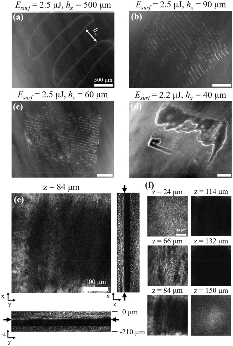
Creation of sub-epithelial voids within scarred vocal folds via ultrafast laser ablation may help in localization of injectable therapeutic biomaterials towards an improved treatment for vocal fold scarring. Several ultrafast laser surgery probes have been developed for precise ablation of surface tissues; however, these probes lack the tight beam focusing required for sub-surface ablation in highly scattering tissues such as vocal folds. Here, we present a miniaturized ultrafast laser surgery probe designed to perform sub-epithelial ablation in vocal folds. The requirement of high numerical aperture for sub-surface ablation, in addition to the small form factor and side-firing architecture required for clinical use, made for a challenging optical design. An Inhibited Coupling guiding Kagome hollow core photonic crystal fiber delivered micro-Joule level ultrashort pulses from a high repetition rate fiber laser towards a custom-built miniaturized objective, producing a 1/e2 focal beam radius of 1.12 ± 0.10 μm and covering a 46 × 46 μm2 scan area. The probe could deliver up to 3.8 μJ pulses to the tissue surface at 40% transmission efficiency through the entire system, providing significantly higher fluences at the focal plane than were required for sub-epithelial ablation. To assess surgical performance, we performed ablation studies on freshly excised porcine hemi-larynges and found that large area sub-epithelial voids could be created within vocal folds by mechanically translating the probe tip across the tissue surface using external stages. Finally, injection of a model biomaterial into a 1 × 2 mm2 void created 114 ± 30 μm beneath the vocal fold epithelium surface indicated improved localization when compared to direct injection into the tissue without a void, suggesting that our probe may be useful for pre-clinical evaluation of injectable therapeutic biomaterials for vocal fold scarring therapy. With future developments, the surgical system presented here may enable treatment of vocal fold scarring in a clinical setting.


Conflict of interest statement

The authors declare no competing interests.

Figures

Figure 1
Figure 1
Overview of ultrafast laser surgery system. (a) Opto-mechanical design of surgery probe. The probe focuses the laser beam (red trace) onto a sub-surface tissue plane using a miniaturized objective consisting of a sapphire window (1), reflective microprism (2), ZnS lens (3), and two CaF2 lenses (4 and 5). All optical components are housed within a 304SS hypodermic tube (6) and distances between the three lenses are set by brass spacers (7). The locus of the scanned Kagome fiber tip (8) is mapped in Zemax to simulate the path of the rays from the focal plane back through the objective. A PMMA insert (9) centered the fiber within the inner cavity of a piezo-electric tube (10). The piezo electric tube (10) was centered within an 304SS inner casing (11) using an accurately turned epoxy plug. The inner casing (11) was centered within the hypodermic tube (6) to align the piezo-HCPCF assembly to the miniaturized objective. Two outer casings (12, 13) were added to secure the backend of the probe to the miniaturized objective. (b) Optical schematic of miniaturized objective. A ray trace depicts different launch angles from the fiber tip through the system. (c) Final assembly and packaging of miniaturized objective in hypodermic tube.
Figure 2
Figure 2
(a) Surgery system with probe integrated into external actuation system. (b) Probe tip placement on inferior porcine VF surface. (c) Experimental setup included a half-wave plate (HWP), polarizing beam splitter (PBS), beam block (BB), fiber coupling lens (CL), five-axis stage (5A), and external actuation system (EAS). Collection optics (CO) were modified based on the resolution and/or output beam size required for the beam profiler (BP), power meter (PM), autocorrelator (AC), or spectrometer (SM).
Figure 3
Figure 3
Kagome fiber characterization. (a) Measured loss and calculated disperion spectra of Kagome fiber. Inset shows en face view of fiber. Scale bar is 50 μm. (b) Measured transmission curves through 6 m long Kagome fiber for 300 fs, 1.1 ps, and 5 ps pulses and for the entire surgery probe at 1.1 ps. (c) Pulse compression ratio (PCR) at fiber output of 300 fs (blue), 1.1 ps (green), and 5 ps (red) pulses as a function of input pulse energy. Data points represent FHWM pulse widths measured with the autocorrelator (AC) while solid lines represent pulse widths predicted from simulations. Error bars represent 95% confidence intervals of sech2 fits to autocorrelator pulse width measurements. (d) Autocorrelator trace of 300 fs pulse at fiber input (dotted line) and output (solid line) for an input pulse energy of 10 μJ. (e) Pulse spectrum of 300 fs pulse at fiber input (dotted line) and output (solid line) for an input pulse energy of 10 μJ. (f) Lissajous scanning simulations showing the effect of lateral translation speed on pulse deposition profile. Translational speed of 1 mm/s results in complete coverage while 2 mm/s and 3 mm/s provide 94% and 81% coverage, respectively. The color bar to the right indicates the number of overlapping pulses throughout the scan area. Laser repetition rate was 500 kHz for data collected in (be).
Figure 4
Figure 4
Optical performance of surgical probe. (a) Focal spot of miniaturized objective imaged with 20 × water immersion objective, 400 mm tube lens, and beam profiler. Beam profile was fit to Gaussian function to determine 1/e2 focal beam radius (w0). Uncertainties represent 95% confidence intervals for the Gaussian fit to the vertical and horizontal profiles. Scale bar is 1 μm. (b) Binary image of 46 × 46 μm2 FOV at the probe focal plane. (c) Ablation of borosilicate glass coverslip with surgical probe. The size of the ablation FOV created on the coverslip agrees well with FOV imaging results. (d) Scanning the coverslip laterally enables formation of an ablation trench across the glass surface. Scale bars are 20 μm.
Figure 5
Figure 5
Tissue ablation performance of surgical probe. Sub-epithelial ablation with (a) Esurf=2.5 μJ, hx=500 μm, (b) Esurf=2.5 μJ, hx=90 μm, (c) Esurf=2.5 μJ, hx=60 μm, and (d) Esurf=2.2 μJ, hx=40 μm. Scale bars are 500 μm. (e) TPAF images of sub-epithelial void created with Esurf=2.2 μJ, hx=40 μm. Center image shows the top of the void 84 μm deep into VF, well within the SLP. Cross sections through the centerlines of the center image are shown below and to the right. Black arrows in cross section images indicate the imaging plane shown in center image. (f) Montage of selected frames from the z-stack. Epithelial cells are visible up to a depth of 60 μm and collagen fibers are visible at deeper depths. The void is centered at 114 μm and extends ± 30 μm. Scale bars are 100 μm.
Figure 6
Figure 6
Biomaterial injection into a sub-epithelial void created with surgery probe in excised porcine VF. (a) Image of a ~ 1 × 2 mm2 sub-epithelial void created using surface pulse energies of Esurf2.2 μJ and x-axis step sizes of hx=40 μm. Total surgery time was ~ 3 min. (b) Void shown in (a) after biomaterial injection. The tissue surface was rinsed with saline and wiped with lens tissue prior to imaging. The injected biomaterial can be seen as the brightly fluorescent volume that remains localized underneath the tissue surface in the sub-epithelial ablation region, shown in (a). The red dotted oval indicates the void size before injection. The ablation void increases in size as the biomaterial is injected into the void. (c) Image of the entire porcine hemilarynx taken with camera phone after biomaterial injection shown in (b). The red region is the injected biomaterial localized within the void. The bright blue region is light from the stereo-microscope. (d) Fluorescence image of biomaterial injection into VF without ablation. Most of the injected volume backflows onto tissue surface. After rinsing and wiping of the tissue surface, we see that a small amount of the biomaterial has non-selectively diffused into the surrounding tissues. Scale bars are 500 μm in (a), (b), (d) and 5 mm in (c).

References

    1. Ramig LO, Verdolini K. Treatment efficacy: Voice disorders. J. Speech. Lang. Hear. Res. 1998;41:S101–S116. doi: 10.1044/jslhr.4101.s101. - DOI - PubMed
    1. Cohen SM, Kim J, Roy N, Asche C, Courey M. Prevalence and causes of dysphonia in a large treatment-seeking population. Laryngoscope. 2012;122:343–348. doi: 10.1002/lary.22426. - DOI - PubMed
    1. Benninger MS, et al. Vocal fold scarring: Current concepts and management. Otolaryngol. Head. Neck Surg. 1996;115:474–482. - PubMed
    1. Hirano S, et al. Histologic characterization of human scarred vocal folds. J. Voice. 2009;23:399–407. doi: 10.1016/j.jvoice.2007.12.002. - DOI - PubMed
    1. Friedrich, G. et al. Vocal fold scars: current concepts and future directions. Consensus report of the Phonosurgery Committee of the European Laryngological Society. Eur. Arch. oto-rhino-laryngology Off. J. Eur. Fed. Oto-Rhino-Laryngological Soc. Affil. with Ger. Soc. Oto-Rhino-Laryngologyṣ—Head Neck Surg. 270, 2491–2507 (2013). - PubMed

Publication types

Substances