Review
. 2022 Nov 22;15(23):8278.
doi: 10.3390/ma15238278.

Metallic Glass-Reinforced Metal Matrix Composites: Design, Interfaces and Properties

Affiliations
Review

Metallic Glass-Reinforced Metal Matrix Composites: Design, Interfaces and Properties

Konstantinos Georgarakis et al. Materials (Basel). .

Abstract

When metals are modified by second-phase particles or fibers, metal matrix composites (MMCs) are formed. In general, for a given metallic matrix, reinforcements differing in their chemical nature and particle size/morphology can be suitable while providing different levels of strengthening. This article focuses on MMCs reinforced with metallic glasses and amorphous alloys, which are considered as alternatives to ceramic reinforcements. Early works on metallic glass (amorphous alloy)-reinforced MMCs were conducted in 1982-2005. In the following years, a large number of composites have been obtained and tested. Metallic glass (amorphous alloy)-reinforced MMCs have been obtained with matrices of Al and its alloys, Mg and its alloys, Ti alloys, W, Cu and its alloys, Ni, and Fe. Research has been extended to new compositions, new design approaches and fabrication methods, the chemical interaction of the metallic glass with the metal matrix, the influence of the reaction products on the properties of the composites, strengthening mechanisms, and the functional properties of the composites. These aspects are covered in the present review. Problems to be tackled in future research on metallic glass (amorphous alloy)-reinforced MMCs are also identified.

Keywords: amorphous alloy; electrical conductivity; interface; mechanical properties; metal matrix composites; metallic glass; microstructure; reinforcement.


Conflict of interest statement

The authors declare no conflict of interest. The funders had no role in the design of the study; in the collection, analyses, or interpretation of data; in the writing of the manuscript, or in the decision to publish the results.

Figures

Figure 1
Figure 1
Schematic of the assembly for hot pressing of the ribbons with metal discs (a) and a radiograph of the hot-pressed sample (b). Reprinted from [29], Copyright (1982), with permission from Springer Nature: Chapman and Hall, Ltd.
Figure 2
Figure 2
High-resolution transmission electron microscopy image of a rapidly solidified Al-4V-2Fe alloy. Amorphous regions surrounded by the interconnected α-Al phase are arrowed. Reprinted from [38], Copyright (1998), with permission from Elsevier.
Figure 3
Figure 3
Microstructure of Ni-Nb-Ta metallic glass ribbon-reinforced Al-Si-Mg alloy matrix composite. Reprinted from [35], Copyright (2004), with permission from Elsevier.
Figure 4
Figure 4
Microstructure of Cu + Ni-Zr-Ti-Si-Sn metallic glass composites obtained via (a) cold rolling and folding of Cu foils with Ni-Zr-Ti-Si-Sn metallic glass ribbons, (b) warm rolling of cold-rolled composites sealed in a Cu tube. Reprinted from [36], Copyright (2004), with permission from Elsevier.
Figure 5
Figure 5
Approaches to the design of metallic glass (amorphous alloy)-reinforced MMCs.
Figure 6
Figure 6
Temperature dependence (heating rate 10 K min−1) of the viscosity of the supercooled liquid for the single-phase Al85Y8Ni5Co2 glassy ribbon (mechanically milled) and for the Al matrix composites with 50 vol.% and 30 vol.% glass reinforcement. Reprinted from [45], Copyright (2008), with permission from Springer Nature.
Figure 7
Figure 7
Differential scanning calorimetry scan for the Mg65Cu20Zn5Y10 metallic glass. Reprinted from [58], Copyright (2014), with permission from Elsevier.
Figure 8
Figure 8
X-ray diffraction (XRD) patterns of the Mg65Cu20Zn5Y10 glass and Al + Mg65Cu20Zn5Y10 composites. Reprinted from [58], Copyright (2014), with permission from Elsevier.
Figure 9
Figure 9
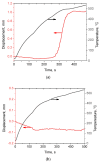
Temperature and displacement versus time during spark plasma sintering (SPS) of the glassy Fe66Cr10Nb5B19 (a) and crystalline Fe62Cr10Nb12B16 (b) alloy powders. Black lines—temperature; red lines—displacement. Reprinted from [82]. This article is an open access article distributed under the terms and conditions of the Creative Commons Attribution (CC BY) license (https://creativecommons.org/licenses/by/4.0/).
Figure 10
Figure 10
Microstructure of the spark plasma sintered composites obtained from (a) Al (coarse)–glassy Fe66Cr10Nb5B19, (b) Al (coarse)–crystalline Fe62Cr10Nb12B16 mixtures, (c) Al (fine)–glassy Fe66Cr10Nb5B19, (d) Al (fine)–crystalline Fe62Cr10Nb12B16 mixtures. (a,c,d) Micrographs of the polished cross-sections, SE images; (b) micrograph of the fracture surface, BSE image. Reprinted from [82]. This article is an open access article distributed under the terms and conditions of the Creative Commons Attribution (CC BY) license (https://creativecommons.org/licenses/by/4.0/).
Figure 11
Figure 11
Schematic of the microstructures of aluminum matrix composites formed using a glassy (a,c) or a crystalline (b,d) alloy reinforcement. Reprinted from [82]. This article is an open access article distributed under the terms and conditions of the Creative Commons Attribution (CC BY) license (https://creativecommons.org/licenses/by/4.0/).
Figure 11
Figure 11
Schematic of the microstructures of aluminum matrix composites formed using a glassy (a,c) or a crystalline (b,d) alloy reinforcement. Reprinted from [82]. This article is an open access article distributed under the terms and conditions of the Creative Commons Attribution (CC BY) license (https://creativecommons.org/licenses/by/4.0/).
Figure 12
Figure 12
Transmission electron microscopy images of the interface in composites obtained via spark plasma sintering of CuCrZr alloy + 30 wt.% Cu50Zr43Al7 metallic glass mixtures at 500 MPa at different temperatures: (a) 693 K and (b) 723 K. Reprinted from [88], Copyright (2022), with permission from Elsevier.
Figure 13
Figure 13
Microstructure of composites obtained from Al 2024 + 40 vol.% Ni60Nb40 mixtures: (a) as-hot-pressed state and (b) heat-treated state. Reprinted from [71], Copyright (2019), with permission from Elsevier.
Figure 14
Figure 14
(a) A micrograph showing a particle of the Fe43.2Co28.8B19.2Si4.8Nb4 metallic glass in the matrix of Al 2024 alloy. The composite was heat-treated. (b) Maps of Al and Cu; the map of Cu shows its concentration at the interface. Reprinted from [78], Copyright (2020), with permission from Elsevier.
Figure 15
Figure 15
Microstructure of the hot-extruded composites obtained from Al 7075 + 8 vol.% Ti52Cu20Ni17Al11 mixtures milled for 10 h (a) and 50 h (b). Reprinted from [67], Copyright (2018), with permission from Elsevier.
Figure 16
Figure 16
XRD patterns of the Ti52Cu20Ni17Al11 metallic glass, Al 7075 + 8 vol.% Ti52Cu20Ni17Al11 mixtures, hot-extruded matrix alloy, and composites obtained from the Al 7075 + 8 vol.% Ti52Cu20Ni17Al11 mixtures milled for 30 h and 50 h. Reprinted from [67], Copyright (2018), with permission from Elsevier.
Figure 17
Figure 17
Compressive yield strength–fracture strain data for Al and Al alloy matrix metallic glass (amorphous alloy)-reinforced composites: ■ Al + Ni70Nb30 [40]; ■ Al + Al85Y8Ni5Co2 [45]; ■ Al 5083 + Al85Ni10La5 [41]; ■ Al 520.0 + Cu54Zr36Ti10 [15]; ■ Al + Mg58Cu28.5Gd11Ag2.5 [60]; ■ Al + Mg65Cu20Zn5Y10 [58]; ■ Al 2024 + Fe73Nb5Ge2P10C6B4 [59]; ● Al + Fe66Cr10Nb5B19 [81]; ● Al-Si-Mg + Ni–Nb–Ta [35]; ● Al + Al-Cu-Ti [64]; ● Al 7075 + Zr65Cu18Ni7Al10 [65]; ● Al 7075 + Ti48Zr7.5Cu39Fe2.5Sn2Si1 [74]; □ Al 6061 + [(Fe1/2Co1/2)75B20Si5]96Nb4 [54]; ● Al 7075 + Ti55.5Cu18.5Ni17.5Al8.5 [76]; ○ Al + Fe50.1Co35.1Nb7.7B4.3Si2.8 [70]; ● AlSi10Mg + Ni60Nb20Ta20 [66]; ✚ Al + Al65Cu16.5Ti18.5 [68]; ●, ● Al 7075 + Ti52Cu20Ni17Al11 [67]; ▲, ▲ Al 2024 + Ni60Nb40 [71]; ▲, ▲, ▲ Al + Cu43Zr43Al7Ag7 [62]; ▲ Al + Zr48Cu36Ag8Al8 [69]; ● Al + Fe74Mo4P10C7.5B2.5Si2 [61].
Figure 18
Figure 18
Tensile yield strength–elongation data for Al and Al alloy matrix composites: ■ Al + Ni60Nb40 [55]; ■ Al-Zn-Ca + Co48Cr15Mo14C15B6Tm2 [73]; ■, ■ Al 2024 + Fe49.9Co35.1Nb7.7B4.5Si2.8 [57]; ■ Al + Al84Gd6Ni7Co3 [56]; ■ Al + Zr48Cu36Ag8Al8 [69].
Figure 19
Figure 19
(a) Engineering stress–strain curves of composites obtained via SPS of CuCrZr alloy + 24 wt.% Cu50Zr43Al7 metallic glass mixtures at 693 K and different pressures; (b) variation in the electrical conductivity of the composites with the sintering pressure. Reprinted from [88], Copyright (2022), with permission from Elsevier.

References

    1. Lloyd D.J. Particle reinforced aluminium and magnesium matrix composites. Int. Mater. Rev. 1994;39:1–23. doi: 10.1179/imr.1994.39.1.1. - DOI
    1. Tjong S.C. Novel nanoparticle-reinforced metal matrix composites with enhanced mechanical properties. Adv. Eng. Mater. 2007;9:639–652. doi: 10.1002/adem.200700106. - DOI
    1. Mortensen A., Llorca J. Metal matrix composites. Annu. Rev. Mater. Res. 2010;40:243–270. doi: 10.1146/annurev-matsci-070909-104511. - DOI
    1. Sweet G.A., Brochu M., Hexemer R.L., Jr., Donaldson I.W., Bishop D.P. Consolidation of aluminum-based metal matrix composites via spark plasma sintering. Mater. Sci. Eng. A. 2015;648:123–133. doi: 10.1016/j.msea.2015.09.027. - DOI
    1. Alaneme K.K., Okotete E.A., Fajemisin A.V., Bodunrin M.O. Applicability of metallic reinforcements for mechanical performance enhancement in metal matrix composites: A review. Arab J. Basic Appl. Sci. 2019;26:311–330. doi: 10.1080/25765299.2019.1628689. - DOI

LinkOut - more resources