Review
. 2022 Nov 28;15(23):8489.
doi: 10.3390/ma15238489.

Chromate-Free Corrosion Protection Strategies for Magnesium Alloys-A Review: Part III-Corrosion Inhibitors and Combining Them with Other Protection Strategies

Affiliations
Review

Chromate-Free Corrosion Protection Strategies for Magnesium Alloys-A Review: Part III-Corrosion Inhibitors and Combining Them with Other Protection Strategies

Bahram Vaghefinazari et al. Materials (Basel). .

Abstract

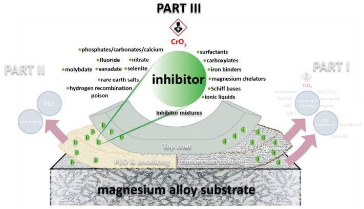
Owing to the unique active corrosion protection characteristic of hexavalent chromium-based systems, they have been projected to be highly effective solutions against the corrosion of many engineering metals. However, hexavalent chromium, rendered a highly toxic and carcinogenic substance, is being phased out of industrial applications. Thus, over the past few years, extensive and concerted efforts have been made to develop environmentally friendly alternative technologies with comparable or better corrosion protection performance to that of hexavalent chromium-based technologies. The introduction of corrosion inhibitors to a coating system on magnesium surface is a cost-effective approach not only for improving the overall corrosion protection performance, but also for imparting active inhibition during the service life of the magnesium part. Therefore, in an attempt to resemble the unique active corrosion protection characteristic of the hexavalent chromium-based systems, the incorporation of inhibitors to barrier coatings on magnesium alloys has been extensively investigated. In Part III of the Review, several types of corrosion inhibitors for magnesium and its alloys are reviewed. A discussion of the state-of-the-art inhibitor systems, such as iron-binding inhibitors and inhibitor mixtures, is presented, and perspective directions of research are outlined, including in silico or computational screening of corrosion inhibitors. Finally, the combination of corrosion inhibitors with other corrosion protection strategies is reviewed. Several reported highly protective coatings with active inhibition capabilities stemming from the on-demand activation of incorporated inhibitors can be considered a promising replacement for hexavalent chromium-based technologies, as long as their deployment is adequately addressed.

Keywords: corrosion; hexavalent chromium; inhibitor; magnesium; self-healing.


Conflict of interest statement

The authors declare no conflict of interest.

Figures

Figure 1
Figure 1
Schematic of review trilogy. This work, as PART III of the review, has been highlighted with more vivid colors, in contrast to the dimmed color of PART I and PART II.
Figure 2
Figure 2
Schematic representation of the mechanism of magnesium corrosion inhibition by aqueous phosphate ions at neutral pH, showing (a) localization of the early stages of corrosion, (b) phosphate speciation in the vicinity of the local cathode, and (c) deposition of an insoluble film [21]. Adapted from [21] with permission from Elsevier.
Figure 3
Figure 3
(a,b) Schematic representation of the mechanism of hydrogen recombination poisoning and (c) decreased corrosion rate in presence of arsenic alloyed with Mg [32]. Adapted from [32] with permission from Elsevier.
Figure 4
Figure 4
Schematic presentation of the corrosion processes and formation of corrosion products of binary Mg0.5Zn or ternary Mg0.5ZnX (X = 0.5Ca or 0.2Ge) alloys in 0.9 wt.% NaCl solutions prepared with deionized water and tap water (as source of Ca2+ and HCO3−). Adapted from [55] with permission from Elsevier.
Figure 5
Figure 5
(a,b) light microscopy images of the WE43 alloy surface after 24 h exposure to 0.05 M NaCl solution without (a) and with (b) 100 mM of Na2MoO4 inhibitor. Numbers and arrows indicate the areas of Raman spectroscopy carried out in the corresponding paper [61] (c) SEM image of as-polished WE43 surface. (d) Surface morphology of the WE43 alloy after 24 h exposure to 0.05 M NaCl solution with 100 mM Na2MoO4. (e) Potentiodynamic polarization curves obtained after 24 h exposure to 0.05 M NaCl without and with molybdate inhibitor. (f) Nyquist EIS plots in 0.05 M NaCl solution without and with varying amounts of Na2MoO4 inhibitor after 24 h of exposure. Adapted from [61] with permission from Elsevier.
Figure 6
Figure 6
(a) Chemical structure of PCCys Schiff-based molecule. (b) Potentiodynamic polarization curves for Mg-Zn-Y-Nd alloy in 0.9 wt.% NaCl solution with and without different concentration of PCCys. (cf) Corrosion morphologies of Mg-Zn-Y-Nd alloy after 7 days immersion in 0.9 wt.% NaCl solution: (c,d) without PCCys, (e,f) with 10−2 M PCCys. Numbers and arrows in (d,f) indicate the areas of EDS analysis carried out in the corresponding paper Adapted from [93] with permission from Elsevier.
Figure 7
Figure 7
(a) Surface morphology of bare AZ21 exposed to 3.5 wt.% NaCl electrolyte containing 8HQ. (b,c) Bode plots of the EIS spectra obtained for the AZ21 Mg during 4 days of immersion in NaCl 3.5 wt.% solution with and without 8HQ, respectively. (d) Cross section view of (a) along with the elemental mappings of the marked area. Adapted from [102] with permission from Elsevier.
Figure 8
Figure 8
Schematic illustration of inhibition mechanism of 8HQ(Mg) layer on a Mg substrate. Note: Mg(HQ)2 in the figure and 8HQ(Mg) in the text refer to the same complex. Adapted from [96] with permission from Elsevier.
Figure 9
Figure 9
Main elemental distribution (Mg, O, S, Mn, and Al) on Mg surface after immersion for 6 h (a) and 48 h (b,c) in 3.5 wt.% NaCl solution with addition of 0.05M SDS. Adapted from [116] with permission from Elsevier.
Figure 10
Figure 10
The schematic representation for the surface adsorption of alkyl carboxylates over different phases of ZE41. Adapted from [112] with permission from Elsevier.
Figure 11
Figure 11
(ad) Adsorption model of Mg surface in NaCl+SDBS solution with high SDBS concentration. (a) Bilayer structure formed by DBS surfactant. (b) Negatively charged DBS and Cl adsorb on positively charged Mg substrate via electrostatic force (the black and white marked “ESF”, respectively, represent electrostatic repulsion and attraction). (c) Competitive adsorption between DBS and Cl (VDW illustrates “van der Waals” force) (d) Formation of hemi-micelle adsorption film. (e,f) Tafel potentiodynamic polarization measurements. (e) Tafel curves recorded in different solutions. (f) Corrosion potential and inhibition efficiency. The labeled cmc1 and cmc2 represent the concentrations of SDBS reaching spherical and rod-like micelles, respectively. Adapted from [128] with permission from Elsevier.
Figure 12
Figure 12
Inhibiting efficiency of top 15 corrosion inhibitors for pure Mg, RE, and Al containing Mg alloys. Based on the data presented in Table 5 of reference [10].
Figure 13
Figure 13
(a) Fragments of in situ Raman spectra recorded on CP-Mg342 in 0.1 M NaCl in absence and in presence of corrosion inhibitors; (b) growth kinetics of Mg(OH)2 recorded on CP-Mg342 in 0.1 M NaCl with or without the corrosion inhibitors; (c) SEM micrographs of CP-Mg342 surface after 30 min contact with flowing 0.1 M NaCl solution with and without 0.05 M inhibitors (a: without inhibitors; b: sodium salicylate (Sal); c: 2,5-pyridin-dicarboxylate (PDCA); d: fumarate (Fum)). Adapted from [158] with permission from Elsevier.
Figure 14
Figure 14
General overview of different categories of corrosion inhibitors for Mg and its alloys with their most effective examples.
Figure 15
Figure 15
SEM micrograph of the surface of GW103 alloy after 24 h of immersion in (a) blank solution; (b) blank solution + 0.1 mM zinc nitrate; (c) blank solution + 0.5 mM APTS–Na and (d) blank solution + 0.5 mM APTS–Na + 0.1 mM zinc nitrate [176]. “Blank solution” is a corrosion testing solution from ASTM D1384, which consists of corrosion test solution: 184 mg/L Na2SO4 + 138 mg/L NaHCO3 + 165 mg/L NaCl. Adapted from [176] with permission from Elsevier.
Figure 16
Figure 16
(I) The morphology of NaMgF3 particles synthesized at varied reactants (NaF: MgCl2) molar ratios of (a) 20:1, (b) 10:1, (c) 2.5:1, and (d) the XRD patterns of the synthesized particles. (II) Morphology of NaMgF3 particles obtained from Mix solutions containing 0.05 M NaF and different molar concentrations of DMA (a) 0.05 M, (b) 0.15 M, and (c) 0.01 M. (III) Potentiodynamic polarization curves of the AM50 specimen immersed in the NaCl background solution (BGS) with and without 0.05 M DMA, 0.05 M NaF, and Mix after 24 h of stabilization. (IV) Schematic illustration of the synergistic corrosion inhibition mechanism of NaF and DMA hybrid inhibitor. Adapted from [45] with permission from Elsevier.
Figure 17
Figure 17
(I) Evolution of low-frequency impedance modulus (0.01 Hz, obtained through EIS) for reference and Ce(DEHP)3-modified coatings during immersion in 0.05M NaCl. (II) Optical micrographs, and SVET (bd) and SIET (fh) maps obtained for different immersion times of the Ce(DEHP)3-modified coating in 0.05M NaCl. Optical micrographs correspond to the beginning of immersion for SVET (a) and SIET (e) measurements. (III) Schematic mechanism of action of Ce(DEHP)3 corrosion inhibitor added to the hybrid epoxy-silane coating for protection of magnesium alloy substrate. R represents the hydrocarbon chain. Adapted from [200] with permission from Elsevier.
Figure 18
Figure 18
SEM surface micrographs of (a,b) MgAl-NO3-LDHs, (c,d) MgAl-MoO42−-LDHs, and (e,f) MgAl-SDS-LDHs. Adapted from [231] with permission from Elsevier.
Figure 19
Figure 19
XRD patterns of AZ31 with Mg-Al-CO32− and Mg-Al-8HQxg (x = 0.25, 0.5 and 1) LDH coatings. Adapted from [228] with permission from Elsevier.
Figure 20
Figure 20
Surface morphologies of anodic films formed in the solutions of 10 g/L NaOH and 18 g/L Na2SiO3 (a) without 8-HQ, with addition of (b) 2 g/L 8-HQ, (c) 5 g/L 8-HQ and (d) 8 g/L 8-HQ under current density 40 mA/cm2, frequency 2000 Hz, duty cycle 20% and anodizing time 3 min. Adapted from [234] with permission from Elsevier.
Figure 21
Figure 21
Schematic illustration of the corrosion protection mechanisms provided by PEO coating with inhibitors.
Figure 22
Figure 22
(a) Schematic representation of the composite protective coating comprising the highly porous anodized or PEO layer enriched with corrosion inhibitors and sealed with the organic coating; (b) Nyquist plots of corresponding ZK30 Mg alloy samples enriched with Ce3+ or 8HQ after 2 weeks in 0.05 M NaCl solution. Adapted from [100] with permission from Elsevier.
Figure 23
Figure 23
Microphotograph of scanned area and distribution of ionic currents (measured by SVET) for the ZE41 magnesium alloy coated with composite film after different immersion time in 0.05 M NaCl solution (a) without loaded 1,2,4 triazole and (b) with loaded 1,2,4 triazole. Adapted and reprinted from [76].
Figure 24
Figure 24
(a) SEM micrographs of the scratched areas of a PEO coating on AM60 alloy sealed with a water-based paint; (b) after immersion in 3.5 wt.% NaCl for 24 h (c) with Ce(NO3)3, (d,f) with Na3PO4, (e,g) with NaVO3. (h) EIS spectra of the scratched composite coatings after immersion in 3.5 wt.% NaCl for 24 h. Adapted from [256] with permission from ECS.
Figure 25
Figure 25
(a) Optical micropgraphs and SVET current density maps of reference CCC and PEO coatings with and without 4MSA inhibitor, acquired during immersion in 0.05 M NaCl. The immersion time is specified in each section of this Figure. (b,c) Evolution of the peak current density, anodic and cathodic, for three types of tested samples during 96 h of immersion in 0.05 M NaCl. “SiPF” refers to the reference PEO sample. Adapted [264] with permission from Elsevier.
Figure 26
Figure 26
(a) Nyquist plots of the PEO sample without (a) and with (b) deposited MnOOH layer immersed in 0.9 wt.% NaCl solution for various times. (c) SEM surface views and EDS spectra of scratches area on the PEO sample without and with deposited MnOOH layer immersed in 0.9 wt.% NaCl solution for various times. PEO-Mn3 denotes the PEO-coated sample immersed in 12 g/L MnCl2 for 9 h. Adapted [273] with permission from Elsevier.
Figure 27
Figure 27
(a) H2 evolved during immersion of the AZ21 sample in 3.5 wt.% NaCl solution containing different concentrations of 2,5PDC. (b) The surface appearance of PEO-coated AZ21 after the failure (duration is specified in each case) in 3.5 wt.% NaCl solution containing different concentration of 2,5PDC. Adapted [159] with permission from Elsevier.

References

    1. Handbook A. Corrosion–Fundamentals, Testing and Protection. Volume 13A ASM International, The Materials Information Society; Materials Park, OH, USA: 2003.
    1. Flick E.W. Corrosion Inhibitors: An Industrial Guide. Noyes Publications; Park Ridge, NJ, USA: 1987.
    1. Sastri V.S. Green Corrosion Inhibitors: Theory and Practice. Wiley; Hoboken, NJ, USA: 2012.
    1. ECHA Authorisation List. [(accessed on 1 September 2017)];2017 Available online: https://echa.europa.eu/authorisation-list.
    1. ECHA Authorisation List with Sunset Dates. [(accessed on 1 September 2017)];2017 Available online: https://echa.europa.eu/authorisation-list?p_p_id=disslists_WAR_disslists....

Grants and funding

LinkOut - more resources