

Investigation of the Effect of Supersonic Flow of Dissociated Nitrogen on ZrB2-HfB2-SiC Ceramics Doped with 10 vol.% Carbon Nanotubes
- PMID: 36500002
- PMCID: PMC9738432
- DOI: 10.3390/ma15238507
Investigation of the Effect of Supersonic Flow of Dissociated Nitrogen on ZrB2-HfB2-SiC Ceramics Doped with 10 vol.% Carbon Nanotubes
Abstract
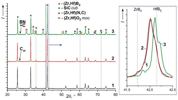
The method of fabricating dense ultra-high temperature ceramic materials ZrB2−HfB2−SiC−CCNT was developed using a combination of sol-gel synthesis and reaction hot pressing approaches at 1800 °C. It was found that the introduction of multilayer nanotubes (10 vol.%) led to an increase in the consolidation efficiency of ceramics (at temperatures > 1600 °C). The obtained ZrB2−HfB2−SiC and ZrB2−HfB2−SiC−CCNT materials were characterized by a complex of physical and chemical analysis methods. A study of the effects on the modified sample ZrB2−HfB2−SiC−CCNT composition speed flow of partially dissociated nitrogen, using a high-frequency plasmatron, showed that, despite the relatively low temperature established on the surface (≤1585 °C), there was a significant change in the chemical composition and surface microstructure: in the near-surface layer, zirconium−hafnium carbonitride, amorphous boron nitride, and carbon were present. The latter caused changes in crucial characteristics such as the emission coefficient and surface catalyticity.
Keywords: CNT; SiC; UHTC; borides; carbon nanotubes; induction plasmatron.
Conflict of interest statement
The authors declare that they have no known competing financial interests or personal relationships that could have appeared to influence the work reported in this paper.
Figures


References
-
- Simonenko E.P., Sevast’yanov D.V., Simonenko N.P., Sevast’yanov V.G., Kuznetsov N.T. Promising Ultra-High-Temperature Ceramic Materials for Aerospace Applications. Russ. J. Inorg. Chem. 2013;58:1669–1693. doi: 10.1134/S0036023613140039. - DOI
-
- Justin J.-F., Julian-Jankowiak A., Guérineau V., Mathivet V., Debarre A. Ultra-High Temperature Ceramics Developments for Hypersonic Applications. CEAS Aeronaut. J. 2020;11:651–664. doi: 10.1007/s13272-020-00445-y. - DOI
-
- Pellegrini C., Balat-Pichelin M., Rapaud O., Bêche E. Oxidation Resistance of Zr- and Hf-Diboride Composites Containing SiC in Air Plasma up to 2600 K for Aerospace Applications. Ceram. Int. 2022;48:2177–2190. doi: 10.1016/j.ceramint.2021.09.310. - DOI
-
- Nisar A., Hassan R., Agarwal A., Balani K. Ultra-High Temperature Ceramics: Aspiration to Overcome Challenges in Thermal Protection Systems. Ceram. Int. 2022;48:8852–8881. doi: 10.1016/j.ceramint.2021.12.199. - DOI
-
- Guérineau V., Vilmart G., Dorval N., Julian-Jankowiak A. Comparison of ZrB2-SiC, HfB2-SiC and HfB2-SiC-Y2O3 Oxidation Mechanisms in Air Using LIF of BO2(G) Corros. Sci. 2020;163:108278. doi: 10.1016/j.corsci.2019.108278. - DOI
Grants and funding
LinkOut - more resources
Full Text Sources
