Review
. 2022 Nov 26;14(23):5147.
doi: 10.3390/polym14235147.

Additive Manufacturing of Polyolefins

Affiliations
Review

Additive Manufacturing of Polyolefins

Fotis Christakopoulos et al. Polymers (Basel). .

Abstract

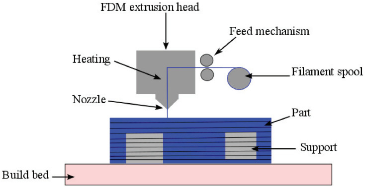
Polyolefins are semi-crystalline thermoplastic polymers known for their good mechanical properties, low production cost, and chemical resistance. They are amongst the most commonly used plastics, and many polyolefin grades are regarded as engineering polymers. The two main additive manufacturing techniques that can be used to fabricate 3D-printed parts are fused filament fabrication and selective laser sintering. Polyolefins, like polypropylene and polyethylene, can, in principle, be processed with both these techniques. However, the semi-crystalline nature of polyolefins adds complexity to the use of additive manufacturing methods compared to amorphous polymers. First, the crystallization process results in severe shrinkage upon cooling, while the processing temperature and cooling rate affect the mechanical properties and mesoscopic structure of the fabricated parts. In addition, for ultra-high-molecular weight polyolefins, limited chain diffusion is a major obstacle to achieving proper adhesion between adjunct layers. Finally, polyolefins are typically apolar polymers, which reduces the adhesion of the 3D-printed part to the substrate. Notwithstanding these difficulties, it is clear that the successful processing of polyolefins via additive manufacturing techniques would enable the fabrication of high-end engineering products with enormous design flexibility. In addition, additive manufacturing could be utilized for the increased recycling of plastics. This manuscript reviews the work that has been conducted in developing experimental protocols for the additive manufacturing of polyolefins, presenting a comparison between the different approaches with a focus on the use of polyethylene and polypropylene grades. This review is concluded with an outlook for future research to overcome the current challenges that impede the addition of polyolefins to the standard palette of materials processed through additive manufacturing.

Keywords: 3D printing; additive manufacturing; fused filament fabrication; polyethylene; polymer processing; polyolefins; polypropylene; selective laser sintering.


Conflict of interest statement

The authors declare no conflict of interest.

Figures

Figure 1
Figure 1
Schematic depiction of the fused filament fabrication process. The filament enters the extrusion head, which heats up the filament coming from the spool, after which the filament is extruded from the nozzle. The material is deposited onto the previously deposited layer to fabricate the desired object. Support material can also be extruded, which is removed afterward, to allow for a higher degree of complexity in the 3D-printed objects. Reproduced with permission [41], Copyright 2017, Elsevier.
Figure 2
Figure 2
Schematic depiction of the laser sintering process inside the building chamber of the 3D printer. Here, the powder feed compartment holds the polymeric powder, and the build compartment is where the deposition of a new layer of powder and the laser scanning and sintering of a new layer of the printed object takes place. The laser passes through a convex lens onto a scanning mirror, which can rotate to move the laser spot along the surface of the deposited layer. Reproduced with permission [19], Copyright 2020, Springer Nature.
Figure 3
Figure 3
The printing direction of the sintered layers, where the layers of a 3D-printed tensile bar are oriented in (a) the x-direction, (b) the y-direction, and (c) the z-direction. F corresponds to the loading direction. Reproduced with permission [72], Copyright 2021, Elsevier.
Figure 4
Figure 4
A schematic outline of the influence the chamber temperature Tch and nozzle temperature Tn have on the consolidation of deposited iPP filaments, i.e., beads, through FFF (a) along the deposited filament and (b) along the cross-section in the ZX-plane. Here, a higher chamber temperature lowers the porosity, described as the gap between deposited filaments, and a higher nozzle temperature increases the length between two deposited filaments and decreases the porosity. Reproduced with permission [83], Copyright 2021, Elsevier.
Figure 5
Figure 5
Differential scanning calorimetry thermograph of neat iPP (Advance3d materials) at a heating and cooling rate of 10 °C min1. The sintering window is 35.1 °C, and the overall degree of crystallinity is 39.58%. Reproduced with permission [91], Copyright 2018, MDPI.
Figure 6
Figure 6
Differential scanning calorimetry thermograph of reactor powder UHMWPE (GUR4120, molecular weight of 4.5 ×10⁶g mol1) at a heating and cooling rate of 10 °C min1. The red solid and red dashed lines correspond to the melting of the as-polymerized and melt-crystallized powder, respectively. The sintering window is approximately 7 °C.
Figure 7
Figure 7
Engineering stress against engineering strain for different laser-sintered UHMWPE samples with laser powers of 6, 8, 10, and 12 W, respectively. Each profile constitutes the average of five samples tested under similar conditions. Reproduced with permission [117], Copyright 2016, EDP Sciences.
Figure 8
Figure 8
(a) Scanning electron microscopy micrographs of four different UHMWPE samples made via SLS printing. (b) Characterization of the consolidation of UHMWPE via SLS printing, where the hatch spacing is shown against the scan speed of the laser. Here, a direct correlation between the characterization and the specific energy density is shown. Reproduced with permission [119], Copyright 2021, Elsevier.

References

    1. Nielsen T.D., Hasselbalch J., Holmberg K., Stripple J. Politics and the plastic crisis: A review throughout the plastic life cycle. Wiley Interdiscip. Rev. Energy Environ. 2020;9:e360. doi: 10.1002/wene.360. - DOI
    1. Amadei A.M., Sanyé-Mengual E., Sala S. Modeling the EU plastic footprint: Exploring data sources and littering potential. Resour. Conserv. Recycl. 2022;178:106086. doi: 10.1016/j.resconrec.2021.106086. - DOI
    1. Agboola O., Sadiku R., Mokrani T., Amer I., Imoru O. Polyolefin Fibres: Structure, Properties and Industrial Applications: Second Edition. Woodhead Publishing; Sawston, UK: 2017. Polyolefins and the environment; pp. 89–133. - DOI
    1. Shonnard D., Tipaldo E., Thompson V., Pearce J., Caneba G., Handler R. Systems analysis for PET and olefin polymers in a circular economy. Procedia CIRP. 2019;80:602–606. doi: 10.1016/j.procir.2019.01.072. - DOI
    1. Vollmer I., Jenks M.J., Roelands M.C., White R.J., van Harmelen T., de Wild P., van der Laan G.P., Meirer F., Keurentjes J.T., Weckhuysen B.M. Beyond Mechanical Recycling: Giving New Life to Plastic Waste. Angew. Chem. Int. Ed. 2020;59:15402–15423. doi: 10.1002/anie.201915651. - DOI - PMC - PubMed

LinkOut - more resources