. 2022 Dec 1;22(23):9348.
doi: 10.3390/s22239348.

Self-Calibration of a Large-Scale Variable-Line-Spacing Grating for an Absolute Optical Encoder by Differencing Spatially Shifted Phase Maps from a Fizeau Interferometer

Affiliations

Self-Calibration of a Large-Scale Variable-Line-Spacing Grating for an Absolute Optical Encoder by Differencing Spatially Shifted Phase Maps from a Fizeau Interferometer

Xin Xiong et al. Sensors (Basel). .

Abstract

A new method based on the interferometric pseudo-lateral-shearing method is proposed to evaluate the pitch variation of a large-scale planar variable-line-spacing (VLS) grating. In the method, wavefronts of the first-order diffracted beams from a planar VLS grating are measured by a commercial Fizeau form interferometer. By utilizing the differential wavefront of the first-order diffracted beam before and after the small lateral shift of the VLS grating, the pitch variation of the VLS grating can be evaluated. Meanwhile, additional positioning errors of the grating in the lateral shifting process could degrade the measurement accuracy of the pitch variation. To address the issue, the technique referred to as the reference plane technique is also introduced, where the least squares planes in the wavefronts of the first-order diffracted beams are employed to reduce the influences of the additional positioning errors of the VLS grating. The proposed method can also reduce the influence of the out-of-flatness of the reference flat in the Fizeau interferometer by taking the difference between the measured positive and negative diffracted wavefronts; namely, self-calibration can be accomplished. After the theoretical analysis and simulations, experiments are carried out with a large-scale VLS grating to verify the feasibility of the proposed methods. Furthermore, the evaluated VLS parameters are verified by comparing them with the readout signal of an absolute surface encoder employing the evaluated VLS grating as the scale for measurement.

Keywords: diffraction gratings; interferometric pseudo-lateral-shearing method; interferometry; optical encoder; self-calibration; variable-line-spacing grating.


Conflict of interest statement

The authors declare no conflict of interest.

Figures

Figure 1
Figure 1
Measurement of the wavefront of the diffracted beam from a large-scale VLS grating: (a) Schematic of the measurement setup; (b) Wavefront of the diffracted beam from a typical VLS grating (The pitch variation subjects to second-order polynomial law).
Figure 2
Figure 2
A new method integrating an interferometric pseudo-lateral-shearing method: (a) A schematic of the measurement procedure for calibration of the VLS parameters of the large-scale VLS grating; (b) A schematic showing the concept of the proposed method based on pseudo-lateral-shearing (In each of the three measurements, the interferometer is fixed with respect to the VLS grating).
Figure 3
Figure 3
Self-calibration of the VLS parameters of the large-scale VLS grating by using the differential diffracted wavefronts before and after the lateral shift (The pitch variation of the grating is subjected to the second-order polynomial in the example).
Figure 4
Figure 4
The proposed reference plane technique: (a) An example showing the plane wavefront influenced by the tilt/tip/piston error after the shift; (b) A schematic showing the procedure of the proposed reference method.
Figure 5
Figure 5
Simulated form of the VLS grating and the reference flat: (a) Simulated out-of-flatness of the VLS grating; (b) Simulated out-of-flatness of the reference flat.
Figure 6
Figure 6
Simulated pitch variation of the VLS grating in the two cases. (a) Simulated pitch variation of the VLS grating in case one; (b) Simulated pitch variation of the VLS grating in case two.
Figure 7
Figure 7
Flow diagram of the simulation procedure.
Figure 8
Figure 8
Reconstructed pitch distribution result of case one using the proposed method without applying the reference plane technique. (a) Evaluated differential phase outputs and its fitting result before the shift with 5% noise level; (b) Evaluated differential phase outputs and its fitting result after the shift with 5% noise level; (c) Given pitch in simulation and reconstructed pitch variation of VLS grating; (d) Difference between the simulation and the reconstruction result.
Figure 9
Figure 9
Reconstructed pitch distribution result of case two by using the proposed pseudo-lateral-shearing and reference plane technique: (a) Evaluated differential phase outputs and its fitting result before the shift with 5% noise level; (b) Evaluated differential phase outputs and its fitting result after the shift with 5% noise level; (c) Given pitch in simulation and reconstructed pitch distribution of VLS grating; (d) Difference between the simulation and the reconstruction result.
Figure 10
Figure 10
Experiment setup: (a) Schematic of the experimental setup with a commercial Fizeau interferometer; (b) Photograph of the experiment setup.
Figure 11
Figure 11
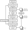
Flow diagram indicating the measurement procedure for the self-calibration of the large-scale VLS grating.
Figure 12
Figure 12
Measured diffracted wavefronts before and after shift (X-direction): (a) Measured positive first-order diffracted wavefront before the shift; (b) Measured negative first-order diffracted wavefront before the shift; (c) Measured positive first-order diffracted wavefront after the shift; (d) Measured negative first-order diffracted wavefront after the shift.
Figure 13
Figure 13
Measured first-order differential diffracted wavefronts before and after shift (X-direction): (a) Measured first-order differential diffracted wavefront before the shift; (b) X-directional cross-sectional profile of the differential wavefront in (a); (c) Difference of the first-order differential diffracted wavefront before and after the shift; (d) X-directional cross-sectional profile of the differential wavefront in (c).
Figure 14
Figure 14
Measured diffracted wavefronts before and after shift (Y-direction): (a) Measured positive first-order diffracted wavefront before the shift; (b) Measured negative first-order diffracted wavefront before the shift; (c) Measured positive first-order diffracted wavefront after the shift; (d) Measured negative first-order diffracted wavefront after the shift.
Figure 15
Figure 15
Measured first-order differential diffracted wavefronts before and after shift (Y-direction): (a) Measured first-order differential diffracted wavefront before the shift; (b) Y-directional cross-sectional profile of the differential wavefront in (a); (c) Difference of the first-order differential diffracted wavefront before and after the shift; (d) Y-directional cross-sectional profile of the differential wavefront in (c).
Figure 16
Figure 16
Evaluated two-dimensional pitch variations of the large-scale VLS grating: (a) X-directional two-dimensional pitch variations; (b) X-directional central cross-section pitch distribution; (c) Y-directional two-dimensional pitch variations; (d) Y-directional central cross-section pitch distribution.
Figure 17
Figure 17
The experimental setup for the evaluation of the reading errors of the optical head in the absolute planar encoder.
Figure 18
Figure 18
Measurement of the encoder errors of the absolute planar encoder and the comparison results: (a) Scanning lines along the VLS grating; (b) X-direction comparison result; (c) Y-direction comparison result.
Figure 19
Figure 19
Differences between the encoder error of the absolute planar encoder and the accumulative results evaluated by using the assessed VLS parameter: (a) Differences between the comparison results along the X-direction with and without applying the proposed method; (b) Differences between the comparison results along the Y-direction with and without applying the proposed method.

References

    1. Gao W., Kim S.W., Bosse H., Haitjema H., Chen Y.L., Lu X.D., Knapp W., Weckenmann A., Estler W.T., Kunzmann H. Measurement technologies for precision positioning. CIRP Ann. Manuf. Technol. 2015;64:773–796. doi: 10.1016/j.cirp.2015.05.009. - DOI
    1. Johnson A.S., Austin D.R., Wood D.A., Brahms C., Gregory A., Holzner K.B., Jarosch S., Larsen E.W., Parker S., Strüber C.S., et al. High-flux soft X-ray harmonic generation from ionization-shaped few-cycle laser pulses. Sci. Adv. 2018;4 doi: 10.1126/sciadv.aar3761. - DOI - PMC - PubMed
    1. De Chuang Y., Shao Y.C., Cruz A., Hanzel K., Brown A., Frano A., Qiao R., Smith B., Domning E., Huang S.W., et al. Modular soft X-ray spectrometer for applications in energy sciences and quantum materials. Rev. Sci. Instrum. 2017;88:013110. doi: 10.1063/1.4974356. - DOI - PubMed
    1. Vishnyakov E.A., Kolesnikov A.O., Pirozhkov A.S., Ragozin E.N., Shatokhin A.N. Aperiodic reflection diffraction gratings for soft X-ray radiation and their application. Quantum Electron. 2018;48:916–929. doi: 10.1070/QEL16707. - DOI
    1. Li X., Zhang J., Zhou Q., Ni K., Pang J., Tian R. Design of a variable-line-spacing grating pattern for spectrometers based on a grating Fresnel device. Opt. Lett. 2016;41:1470. doi: 10.1364/OL.41.001470. - DOI - PubMed

LinkOut - more resources