Tensor image registration library: Deformable registration of stand-alone histology images to whole-brain post-mortem MRI data
- PMID: 36509214
- PMCID: PMC10933796
- DOI: 10.1016/j.neuroimage.2022.119792
Tensor image registration library: Deformable registration of stand-alone histology images to whole-brain post-mortem MRI data
Abstract
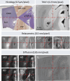
Background: Accurate registration between microscopy and MRI data is necessary for validating imaging biomarkers against neuropathology, and to disentangle complex signal dependencies in microstructural MRI. Existing registration methods often rely on serial histological sampling or significant manual input, providing limited scope to work with a large number of stand-alone histology sections. Here we present a customisable pipeline to assist the registration of stand-alone histology sections to whole-brain MRI data.
Methods: Our pipeline registers stained histology sections to whole-brain post-mortem MRI in 4 stages, with the help of two photographic intermediaries: a block face image (to undistort histology sections) and coronal brain slab photographs (to insert them into MRI space). Each registration stage is implemented as a configurable stand-alone Python script using our novel platform, Tensor Image Registration Library (TIRL), which provides flexibility for wider adaptation. We report our experience of registering 87 PLP-stained histology sections from 14 subjects and perform various experiments to assess the accuracy and robustness of each stage of the pipeline.
Results: All 87 histology sections were successfully registered to MRI. Histology-to-block registration (Stage 1) achieved 0.2-0.4 mm accuracy, better than commonly used existing methods. Block-to-slice matching (Stage 2) showed great robustness in automatically identifying and inserting small tissue blocks into whole brain slices with 0.2 mm accuracy. Simulations demonstrated sub-voxel level accuracy (0.13 mm) of the slice-to-volume registration (Stage 3) algorithm, which was observed in over 200 actual brain slice registrations, compensating 3D slice deformations up to 6.5 mm. Stage 4 combined the previous stages and generated refined pixelwise aligned multi-modal histology-MRI stacks.
Conclusions: Our open-source pipeline provides robust automation tools for registering stand-alone histology sections to MRI data with sub-voxel level precision, and the underlying framework makes it readily adaptable to a diverse range of microscopy-MRI studies.
Keywords: Brain; Histology; Human; MRI; Post-mortem; Registration.
Copyright © 2022. Published by Elsevier Inc.
Conflict of interest statement
Declaration of Competing Interest The authors declare no conflict of interest. None of the above-mentioned funding bodies were directly involved in the design of the study, nor in the collection, analysis, or interpretation of the data.
Figures


Similar articles
-
Developing 3D microscopy with CLARITY on human brain tissue: Towards a tool for informing and validating MRI-based histology.Neuroimage. 2018 Nov 15;182:417-428. doi: 10.1016/j.neuroimage.2017.11.060. Epub 2017 Nov 28. Neuroimage. 2018. PMID: 29196268 Free PMC article.
-
3D volume reconstruction from serial breast specimen radiographs for mapping between histology and 3D whole specimen imaging.Med Phys. 2017 Mar;44(3):935-948. doi: 10.1002/mp.12077. Med Phys. 2017. PMID: 28064435 Free PMC article.
-
Registration of in-vivo to ex-vivo MRI of surgically resected specimens: a pipeline for histology to in-vivo registration.J Neurosci Methods. 2015 Feb 15;241:53-65. doi: 10.1016/j.jneumeth.2014.12.005. Epub 2014 Dec 13. J Neurosci Methods. 2015. PMID: 25514760
-
Dissecting the pathobiology of altered MRI signal in amyotrophic lateral sclerosis: A post mortem whole brain sampling strategy for the integration of ultra-high-field MRI and quantitative neuropathology.BMC Neurosci. 2018 Mar 13;19(1):11. doi: 10.1186/s12868-018-0416-1. BMC Neurosci. 2018. PMID: 29529995 Free PMC article.
-
Development of a registration framework to validate MRI with histology for prostate focal therapy.Med Phys. 2015 Dec;42(12):7078-89. doi: 10.1118/1.4935343. Med Phys. 2015. PMID: 26632061
Cited by
-
Hippocampal connectivity patterns echo macroscale cortical evolution in the primate brain.Nat Commun. 2024 Jul 16;15(1):5963. doi: 10.1038/s41467-024-49823-8. Nat Commun. 2024. PMID: 39013855 Free PMC article.
-
SlicesMapi: An Interactive Three-Dimensional Registration Method for Serial Histological Brain Slices.Neuroinformatics. 2025 Apr 16;23(2):28. doi: 10.1007/s12021-025-09724-7. Neuroinformatics. 2025. PMID: 40240690
-
Linking microscopy to diffusion MRI with degenerate biophysical models: An application of the Bayesian EstimatioN of CHange (BENCH) framework.Imaging Neurosci (Camb). 2025 Jul 24;3:IMAG.a.85. doi: 10.1162/IMAG.a.85. eCollection 2025. Imaging Neurosci (Camb). 2025. PMID: 40800990 Free PMC article.
-
Precise MRI-histology coregistration of paraffin-embedded tissue with blockface imaging.Imaging Neurosci (Camb). 2025 Aug 8;3:IMAG.a.106. doi: 10.1162/IMAG.a.106. eCollection 2025. Imaging Neurosci (Camb). 2025. PMID: 40800888 Free PMC article.
-
An open resource combining multi-contrast MRI and microscopy in the macaque brain.Nat Commun. 2023 Jul 19;14(1):4320. doi: 10.1038/s41467-023-39916-1. Nat Commun. 2023. PMID: 37468455 Free PMC article.
References
-
- Alegro, M., Amaro-Jr, E., Loring, B., Heinsen, H., Alho, E., Zollei, L., Ushizima, D., Grinberg, L.T.; Proceedings of the IEEE Conference on Computer Vision and Pattern Recognition (CVPR) Workshops, 2016, pp. 194-202.
-
- Yushkevich P.A., Wisse L., Adler D., et al., A framework for informing segmentation of in vivo MRI with information derived from ex vivo imaging: Application in the medial temporal lobe. Annu Int Conf IEEE Eng Med Biol Soc. 2016 Aug;2016:6014-6017. doi: 10.1109/EMBC.2016.7592099. PMID: 28269623; PMCID: PMC5603287. - PMC - PubMed
-
- Alegro, M., et al. Automating whole brain histology to MRI registration: implementation of a computational pipeline. arXiv e-prints, 2019.
-
- Ali S., et al. Rigid and non-rigid registration of polarized light imaging data for 3D reconstruction of the temporal lobe of the human brain at micrometer resolution. Neuroimage. 2018;181:235–251. - PubMed
Publication types
MeSH terms
Grants and funding
LinkOut - more resources
Full Text Sources
Medical
Research Materials

