Review
. 2022 Oct 30;13(48):14246-14263.
doi: 10.1039/d2sc04945g. eCollection 2022 Dec 14.

Anode optimization strategies for aqueous zinc-ion batteries

Affiliations
Review

Anode optimization strategies for aqueous zinc-ion batteries

Yiyang Zhang et al. Chem Sci. .

Abstract

Zinc-ion batteries (ZIBs) have received much research attention due to their advantages of safety, non-toxicity, simple manufacture, and element abundance. Nevertheless, serious problems still remain for their anodes, such as dendrite development, corrosion, passivation, and the parasitic hydrogen evolution reaction due to their unique aqueous electrolyte system constituting the main issues that must be addressed, which are blocking the further advancement of anodes for Zn-ion batteries. Herein, we conduct an in-depth analysis of the problems that exist for the zinc anode, summarize the main failure types and mechanisms of the zinc anode, and review the main modification strategies for the anode from the three aspects of the electrolyte, anode surface, and anode host. Furthermore, we also shed light on further modification and optimization strategies for the zinc anode, which provide directions for the future development of anodes for zinc-ion batteries.


Conflict of interest statement

There are no conflicts to declare.

Figures

Fig. 1
Fig. 1. (a) Schematic illustration of the working principle of ZIBs. Adapted from ref. . Copyright 2020, Chem. Soc. Rev. (b) Representative cathode materials. Adapted from ref. . Copyright 2021, Wiley-VCH. (c) Schematic diagram of interactions with aqueous electrolyte on the zinc anode surface.
Fig. 2
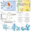
Fig. 2. (a) Schematic illustration of the Zn2+-solvation structure. Adapted from ref. . Copyright 2020, Wiley-VCH. (b) Illustration of the zinc plating process. Adapted from ref. . Copyright 2022, Wiley-VCH. (c) Changes in free energy during Zn nucleation. Adapted from ref. . Copyright 2020, Wiley. (d) Schematic illustration of zinc dendrites. Adapted from ref. . Copyright 2015, Springer Nature. Morphology of dendrites: (e) needle-shaped dendrites. (f) Tree-shaped dendrites. (g) Moss-shaped dendrites. Adapted from ref. . Copyright 2019, Energy Chem.
Fig. 3
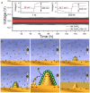
Fig. 3. (a) Demonstration of tip effects in the form of electric field simulations. Adapted from ref. . Copyright 2019, Wiley. Dendrite growth of Li simulated by the phase-field model: (b) evolution of the order parameter, (c) concentration of Li+ and (d) electric potential. Adapted from ref. . Copyright 2015, Elsevier.
Fig. 4
Fig. 4. Schematic plots are shown for gradients in the ion concentration in (a) a strong concentration gradient and (b) a mild concentration gradient with corresponding metal morphologies near the electrode surface. Adapted from ref. . Copyright 2019, AAAS. (c) Illustration of the effect of concentration polarization on zinc deposition. Adapted from ref. . Copyright 2022, Wiley-VCH.
Fig. 5
Fig. 5. Schematic illustration of the Zn deposition process. (a) A uniform and dendrite-free zinc morphology is enabled by more and smaller nuclei. (b) Zn dendrites develop when there are few and random nuclei. Adapted from ref. . Copyright 2022, Wiley-VCH GmbH. (c) Effect of the 3D structure on zinc deposition. Adapted from ref. . Copyright 2022, Wiley-VCH GmbH. (d) Effect of the initial wetting angles on the following deposition process. Adapted from ref. . Copyright 2014, Elsevier Ltd. (e) The models of the affinity between different substrates and zinc. (f) Calculated binding energies between different substrates and zinc. Adapted from ref. . Copyright 2019, Wiley-VCH GmbH. (g) The epitaxial electrodeposition of Zn metal. (h) Morphology of zinc deposits on stainless steel. (i) Illustration of the uneven electrodeposition of Zn. (j) Morphology of zinc deposits on graphene-coated stainless steel. Adapted from ref. . Copyright 2019, AAAS.
Fig. 6
Fig. 6. The open-circuit energy diagram of (a) organic electrolytes and (b) aqueous electrolytes. Eg is the ESW of electrolyte, μ is the redox potential of the electrode, and Φ is the work function of the electrode. (c) Pourbaix diagram of zinc in an aqueous environment, taking both the HER and OER into consideration. Adapted from ref. . Copyright 2016, Elsevier. (d) The ESW and water reactions in aqueous electrolyte. Adapted from ref. . Copyright 2022, Wiley-VCH. (e) Changes in free energy during the HER/OER. (f) The chemical routes and challenges of the Zn anode under alkaline conditions. Adapted from ref. . Copyright 2016, Wiley-VCH. (g) Hydrogen evolution on the electrode surface. Adapted from ref. . Copyright 2021, Wiley-VCH.
Fig. 7
Fig. 7. (a) Galvanostatic charge–discharge curves in different electrolytes. Adapted from ref. . Copyright 2021, American Chemical Society. (b) The self-healing electrostatic shield mechanism. Adapted from ref. . Copyright 2013, American Chemical Society.
Fig. 8
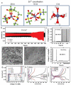
Fig. 8. (a) Solvation structures of Zn2+ in 1 M Zn(TFSI)2 and various LiTFSI concentrations (5 M, 10 M, and 20 M). Adapted from ref. . Copyright 2018, Springer Nature. (b) The plating/stripping of zinc in ZnCl2. Coulombic efficiency (CE) of zinc plating/stripping in (c) 5 M and (f) 30 M ZnCl2 electrolytes. Scanning electron microscope (SEM) images of the zinc anode in (d) 5 M and (e) 30 M ZnCl2. (g) The electrochemical stability window of ZnCl2 at various concentrations. Adapted from ref. . Copyright 2018, The Royal Society of Chemistry. The corresponding voltage profiles of (h) 3 M and (i) 30 M ZnCl2. Adapted from ref. . Copyright 2021, Wiley-VCH.
Fig. 9
Fig. 9. (a) The energy potential changes corresponding to different distances. (b) The transport and reduction of Zn2+ ions in 2 M ZnSO4 and in 0.05 mM tetrabutylammonium sulphate (TBA2SO4) in 2 M ZnSO4 electrolyte. Adapted from ref. . Copyright 2020, American Chemical Society. SEM images of (c) fresh zinc foil and the as deposited zinc anode (d) without additives and (e) with a sodium dodecylbenzene sulphonate (SDBS) additive. (f) XRD patterns of fresh zinc foil and the as deposited zinc anode with and without the SDBS additive. Measurements of contact angles on the LiFePO4 (LFP) electrode/electrolyte interface with (h) or without (g) SDBS additive. Adapted from ref. . Copyright 2019, Wiley-VCH.
Fig. 10
Fig. 10. (a) Nuclear magnetic resonance (NMR) spectra of ether groups with different polyethylene oxide (PEO) contents. (b) The Zn plating process accompanied by dendritic growth and H2 evolution. (c) The effect of PEO polymer molecules on the anode region. Adapted from ref. . Copyright 2020, Wiley-VCH. (d) Schematic illustration of the ZnSO4–glucose system and Zn2+ solvation structure. (e) Electrostatic potential of Zn2+–6H2O (left) and glucose–Zn2+–5H2O (right) solvation structures. Schematic illustration of zinc deposition of (f) ZnSO4, (g) ZnSO4–glucose electrolyte, and (h–k) corresponding SEM images. Adapted from ref. . Copyright 2021, Wiley-VCH.
Fig. 11
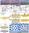
Fig. 11. Interfacial reactions on the zinc anode: (a) hydrogen evolution process, (b) passivation and corrosion. (c) The role of water-in-DES electrolyte. Adapted from ref. . Copyright 2019, Elsevier Ltd. (d) Schematic illustration of the interaction of a lithium-based DES (L-DES)/H2O electrolyte system and the H2O molecule. (e) Illustration of morphology change in the zinc anode during the zinc stripping/electroplating cycle with and without the diethyl ether (Et2O) additive. Adapted from ref. . Copyright 2019, Elsevier. (f) Illustration of alcohol-based material additives. Adapted from ref. . Copyright 2022, Wiley-VCH. (g) Schematic illustration of solvated Zn2+ and surface evolution in H2O (left) and DMSO–H2O (right) systems. Adapted from ref. . Copyright 2022, American Chemical Society.
Fig. 12
Fig. 12. Diagram of the composition of an all-solid-state zinc-ion battery. Adapted from ref. . Copyright 2018, Royal Society of Chemistry.
Fig. 13
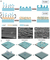
Fig. 13. (a) Synthesis of HPE. Adapted from ref. . Copyright 2018, Royal Society of Chemistry. (b) Mechanisms of deposition behaviours of ZnSO4 electrolytes, water@ZnMOF-808-solid-state electrolyte (WZM), and hybrid ZnSO4@MOF-808 (HZM) electrolyte. Adapted from ref. . Copyright 2018 Elsevier Ltd.
Fig. 14
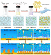
Fig. 14. (a) Protective effect of the PVB layer on the Zn anode. Adapted from ref. . Copyright 2022, Wiley-VCH. (b) The positive effect of the TiO2 coating. Adapted from ref. . Copyright 2018, Wiley-VCH. (c) Computational simulations of Zn absorption on various crystal planes. (d) Interaction of different exposure surfaces between Zn and TiO2. (e and f) TEM images of F-TiO2. (g) Binding energies between zinc atoms with different facets. (h) The deposition behaviour of zinc on various coating layers. Adapted from ref. . Copyright 2018, Nature Communications.
Fig. 15
Fig. 15. Zn deposition process on (a) the unprocessed Zn anode and (b) Zn–rGO anode. SEM images of rGO coating (c) before cycling and (d and e) after cycling. Adapted from ref. . Copyright 2019, Elsevier. (f) Zn plating process with PA coating. Adapted from ref. . Copyright 2019, The Royal Society of Chemistry.
Fig. 16
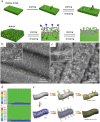
Fig. 16. (a) Electro-plating/stripping process of pristine zinc and the 3D dual-channel porous Zn. Adapted from ref. . Copyright 2020, Elsevier. SEM images of (b) CNT and (c) Zn/CNT. (d) Electric field distribution models for the Zn-CC and Zn-CNT anodes after zinc nucleation. (e) Illustration of zinc plating on Zn-CC and Zn-CNT anodes. Adapted from ref. . Copyright 2019, Wiley-VCH.
Fig. 17
Fig. 17. (a) Photograph of stainless-steel mesh, zinc flake, zinc/stainless-steel mesh. (b) FESEM image of Zn/SS mesh. (c) XRD pattern of zinc/SS mesh. Adapted from ref. . Copyright 2019, Elsevier. Adsorption energy of (d) carbon and (e) Sn. Adapted from ref. . Copyright 2019, WILEY.
Fig. 18
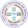
Fig. 18. The as-summarized strategies toward Zn dendrite protection.

References

    1. Larcher D. Tarascon J.-M. Nat. Chem. 2015;7:19–29. doi: 10.1038/nchem.2085. - DOI - PubMed
    1. Notter D. A. Gauch M. Widmer R. Wäger P. Stamp A. Zah R. Althaus H.-J. Environ. Sci. Technol. 2010;44:6550–6556. doi: 10.1021/es903729a. - DOI - PubMed
    1. Hannan M. A. Hoque M. M. Mohamed A. Ayob A. Renewable Sustainable Energy Rev. 2017;69:771–789. doi: 10.1016/j.rser.2016.11.171. - DOI
    1. Telaretti E. Dusonchet L. Renewable Sustainable Energy Rev. 2017;75:380–392. doi: 10.1016/j.rser.2016.11.003. - DOI
    1. Tong Y. Liang J. Liu H. K. Dou S. X. Energy Storage Mater. 2019;20:176–187. doi: 10.1016/j.ensm.2019.04.031. - DOI