Review
. 2022 Dec 12;10(12):3224.
doi: 10.3390/biomedicines10123224.

Three-Dimensional Digital Light-Processing Bioprinting Using Silk Fibroin-Based Bio-Ink: Recent Advancements in Biomedical Applications

Affiliations
Review

Three-Dimensional Digital Light-Processing Bioprinting Using Silk Fibroin-Based Bio-Ink: Recent Advancements in Biomedical Applications

Md Tipu Sultan et al. Biomedicines. .

Abstract

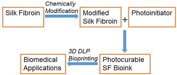
Three-dimensional (3D) bioprinting has been developed as a viable method for fabricating functional tissues and organs by precisely spatially arranging biomaterials, cells, and biochemical components in a layer-by-layer fashion. Among the various bioprinting strategies, digital light-processing (DLP) printing has gained enormous attention due to its applications in tissue engineering and biomedical fields. It allows for high spatial resolution and the rapid printing of complex structures. Although bio-ink is a critical aspect of 3D bioprinting, only a few bio-inks have been used for DLP bioprinting in contrast to the number of bio-inks employed for other bioprinters. Recently, silk fibroin (SF), as a natural bio-ink material used for DLP 3D bioprinting, has gained extensive attention with respect to biomedical applications due to its biocompatibility and mechanical properties. This review introduces DLP-based 3D bioprinting, its related technology, and the fabrication process of silk fibroin-based bio-ink. Then, we summarize the applications of DLP 3D bioprinting based on SF-based bio-ink in the tissue engineering and biomedical fields. We also discuss the current limitations and future perspectives of DLP 3D bioprinting using SF-based bio-ink.

Keywords: bio-ink; biomedical application; digital light processing; silk fibroin; three-dimensional bioprinting.


Conflict of interest statement

The authors declare no conflict of interest.

Figures

Figure 1
Figure 1
Schematic overview of the biomedical application of the SF-based bio-ink via 3D DLP printing.
Figure 2
Figure 2
Schematic illustration of DLP-printing process. DMD: Digital micromirror device. Adapted from [39] with permission from Elsevier.
Figure 3
Figure 3
The fabrication process of SF bio-ink for DLP printing. (a) SF molecules were modified with the addition of GMA by methacrylation. (b) Graphical illustration of methacrylation of SF. GMA was added dropwise into the dissolved SF solution in LiBr (9.5 M) and mixed with continuous stirring at 60 °C for 3 h. Then, it was dialyzed against distilled water for 4 days and freeze-dried. Finally, LAP was put into a GMA-modified SF solution. Adapted from [43] with permission from Springer Nature.
Figure 4
Figure 4
Sil-MA bio-ink’s printability via DLP bioprinter. (a) The simulated scaffold and the Eiffel Tower; (l) images of the CAD portraying the scaffolds and Eiffel Tower and (r) printed pictures. (b) Human ear and brain mirrored structures; (l) the images of the CAD showing the human ear and brain and (r) printed pictures. Printed constructs were not broken when firmly compacted using fingers, and when fingers were relaxed, they reverted to their primary structures. (c) The trachea, heart, lung, and blood vessels imitated morphology; (l) the CAD pictures representing human trachea, heart, lung, and blood vessels and (r) printed pictures at several angles. Printed yields using Sil-MA by DLP displayed complex constructions imitating their CAD pictures, e.g., arteries and veins. Scale bar indicates 1. Adapted from [43] with authorization from Springer Nature.
Figure 4
Figure 4
Sil-MA bio-ink’s printability via DLP bioprinter. (a) The simulated scaffold and the Eiffel Tower; (l) images of the CAD portraying the scaffolds and Eiffel Tower and (r) printed pictures. (b) Human ear and brain mirrored structures; (l) the images of the CAD showing the human ear and brain and (r) printed pictures. Printed constructs were not broken when firmly compacted using fingers, and when fingers were relaxed, they reverted to their primary structures. (c) The trachea, heart, lung, and blood vessels imitated morphology; (l) the CAD pictures representing human trachea, heart, lung, and blood vessels and (r) printed pictures at several angles. Printed yields using Sil-MA by DLP displayed complex constructions imitating their CAD pictures, e.g., arteries and veins. Scale bar indicates 1. Adapted from [43] with authorization from Springer Nature.
Figure 5
Figure 5
Schematic presentation of chondrocyte-encapsulated SF-GMA hydrogel implantation and endoscopic evaluation of rabbit trachea 6 weeks post-implantation. (A) Artificial trachea was fabricated using a DLP printer with chondrocyte-encapsulated SF-GMA and cultivated for 1 week in vitro. (B) (a,b) After surgery and elimination of the incised portion of the trachea, (c) fabricated trachea was transplanted. Scale bars present 5 mm. (C) Endoscopy was performed after 2, 4, and 6 weeks from trachea implantation. SF-GMA hydrogel exhibited the inner length progressively increased after implantation, and surrounding tissues developed in the operating area after 6 weeks of transplantation. Adapted from [75] with permission from Elsevier.
Figure 6
Figure 6
Implantation of the 4D-bioprinted trachea after in vitro culture. (a) Culture of 4D-bioprinted trachea in vitro. Shape morphing was achieved via in vitro culture: scale bars, 1 cm. (b) Transplantation of the fabricated trachea. The fabricated trachea was transplanted into an injured trachea rabbit model. Scale bars, 1 cm. (c) Bronchoscopic pictures of the intrinsic trachea and fabricated trachea at 1, 2, 4, 6 and 8 weeks post-implantation. Arrows indicate transplanted trachea. (d) Masson’s trichrome (MT) staining. The 4D-bioprinted trachea (marked as asterisks and dotted lines) was identified on the transplanted site: scale bars, 1 mm (1 cm for small boxes images). The area of the regenerated epithelium is marked as E and a dotted line with an arrowhead. (e) HE staining. Neo-respiratory epithelium (marked as E and short arrow) was identified at 2 weeks post-surgery. Scale bars, 100 μm. (f) Safranin O staining (immature cartilage is marked with a short arrow). This neo-cartilage had a greater cellular density and less dense sulfated glycosaminoglycan staining than normal tracheal cartilage: scale bars, 250 μm. Adapted from [39] with permission from Elsevier.
Figure 7
Figure 7
The fabrication process of magnetic hydrogel and the effect of magnetic bioreactor on magnetic hydrogel encapsulated myoblast cells. (a). Graphical presentation of the construction processes of the magnetic bioreactor in the 3D DLP printer. Silk-GMA + IO was used as a base layer bio-ink, while the top layers were printed with Gel-GMA + myoblast cells. Silk-GMA: methacrylated SF, Gel-GMA: methacrylated gelatin, GMA: glycidyl methacrylate, IO and O=Fe=O: iron oxide. (b). Fluorescence pictures exhibited myosin (MHC-green) and α-SMA (red) expressions for C2C12 cultured hydrogel in both static and stretched conditionThe alignment of the myotubes and α-SMA was similar to the direction of hydrogel. Adapted from [103] with the permission from IOP Publishing Ltd.
Figure 8
Figure 8
Printability test and FSGMA bio-ink for in vivo cell tracking. (A) FSGMA bio-ink’s printability. (a) The human brain, ear, hand, lung, and organs under bright and fluorescent fields. (b) Human trunk was printed with photocurable resin, and the internal organs were printed with FSGMA using DLP printer. Left side (bright field) and right side (fluorescence field). (c) Fluorescent image of the Hallym University logo and a mini human brain constructed using FSGMA. Scale bars present 150 μm. (B) Histological study of the FSGMA and SGMA hydrogel-encapsulated PKH26-tagged NIH3T3 cells. NT: native tissue and HL: hydrogel. White arrows indicate the presence of cell movement. Adapted from [114] with permission from Elsevier.

Similar articles

Cited by

References

    1. Murphy S.V., Atala A. 3D bioprinting of tissues and organs. Nat. Biotechnol. 2014;32:773–785. doi: 10.1038/nbt.2958. - DOI - PubMed
    1. Campbell T.A., Ivanova O.S. 3D printing of multifunctional nanocomposites. Nano Today. 2013;8:119–120. doi: 10.1016/j.nantod.2012.12.002. - DOI
    1. Saleh Alghamdi S., John S., Roy Choudhury N., Dutta N.K. Additive Manufacturing of Polymer Materials: Progress, Promise and Challenges. Polymers. 2021;13:753. doi: 10.3390/polym13050753. - DOI - PMC - PubMed
    1. Gu B.K., Choi D.J., Park S.J., Kim M.S., Kang C.M., Kim C.H. 3-dimensional bioprinting for tissue engineering applications. Biomater Res. 2016;20:12. doi: 10.1186/s40824-016-0058-2. - DOI - PMC - PubMed
    1. Wong K.V., Hernandez A. A Review of Additive Manufacturing. ISRN Mech. Eng. 2012;2012:208760. doi: 10.5402/2012/208760. - DOI

LinkOut - more resources