Review
. 2022 Dec 9;15(24):8820.
doi: 10.3390/ma15248820.

Electrospun Conducting Polymers: Approaches and Applications

Affiliations
Review

Electrospun Conducting Polymers: Approaches and Applications

Mariana Acosta et al. Materials (Basel). .

Abstract

Inherently conductive polymers (CPs) can generally be switched between two or more stable oxidation states, giving rise to changes in properties including conductivity, color, and volume. The ability to prepare CP nanofibers could lead to applications including water purification, sensors, separations, nerve regeneration, wound healing, wearable electronic devices, and flexible energy storage. Electrospinning is a relatively inexpensive, simple process that is used to produce polymer nanofibers from solution. The nanofibers have many desirable qualities including high surface area per unit mass, high porosity, and low weight. Unfortunately, the low molecular weight and rigid rod nature of most CPs cannot yield enough chain entanglement for electrospinning, instead yielding polymer nanoparticles via an electrospraying process. Common workarounds include co-extruding with an insulating carrier polymer, coaxial electrospinning, and coating insulating electrospun polymer nanofibers with CPs. This review explores the benefits and drawbacks of these methods, as well as the use of these materials in sensing, biomedical, electronic, separation, purification, and energy conversion and storage applications.

Keywords: conducting polymers; electrospinning; nanocomposite; nanofibers.


Conflict of interest statement

The authors declare no conflict of interest.

Figures

Figure 1
Figure 1
Chemical structures of the repeat units of some representative CPs; from left to right: polyacetylene (PA), polypyrrole (PPy), polythiophene (PT), polyaniline (PANI), poly(phenylene vinylene) (PPV), and poly(3,4-ethylenedioxythiophene (PEDOT).
Figure 2
Figure 2
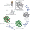
This review article summarizes methods of preparation of CP nanofibers and their application in several areas.
Figure 3
Figure 3
Reversible oxidation and reduction processes form resonance-delocalized electrons and cations (holes) along the backbone of CPs such as PEDOT. Redox processes, which are typically reversible, allow interconversion among neutral polymers (top), radical cations known as polarons (middle), and dications known as bipolarons (bottom). Reprinted from Ref. [45], available at https://www.mdpi.com/1996-1944/12/16/2629; accessed on 1 December 2022.
Figure 4
Figure 4
Left: General structure of poly(3-alkylthiophenes) (P3AT); Right: poly(3-hexylthiophene) (P3HT).
Figure 5
Figure 5
Left: Structure of poly(3,4-ethylenedioxythiophene (PEDOT); Right: structure of PEDOT:PSS.
Figure 6
Figure 6
A typical electrospinning set up [130] using (a) a static grounded collector plate and (b) a grounded rotating drum collector. Reprinted from Ref. [130], available at https://doi.org/10.3390/ma10111238; accessed on 1 December 2022.
Figure 7
Figure 7
Increasing viscosity or conductivity (charge density) reduces bead formation [135]. Top: Scanning electron micrographs (SEMs) of electrospun aqueous poly(ethylene oxide (PEO). The horizontal edge of each image is 20 µm long: (A) 1.5 wt.% PEO, 32 cP; (B) 3 wt.% PEO, 289 cP; (C) 4 wt.% PEO, 1250 cP. Bottom: Electrospun 3 wt.% PEO with increasing NaCl content: (D) 15 ppm NaCl, 1.23 C·L−1; (E) 300 ppm NaCl, 3.03 C·L−1; (F) 1500 ppm NaCl, 28.8 C·L−1. Reprinted from Ref. [135], Copyright 1999, with permission from Elsevier.
Figure 8
Figure 8
Synthetic polymers commonly used for electrospinning include: polyethylene (PE), polypropylene (PP), poly(vinyl chloride) (PVC), poly(acrylonitrile) (PAN), poly(ethylene oxide) (PEO), polycaprolactone (PCL), polycaprolactam (also known as nylon 6 and polyamide 6, PA-6), poly(lactic-co-glycolic acid) (PLGA), polystyrene (PS), and poly(methyl methacrylate) (PMMA).
Figure 9
Figure 9
SEMs of electrospun collagen [157]. (A) Randomly oriented fibrils generated at less than 500 rpm. (B) Aligned fibrils generated at 4500 rpm. Reprinted and adapted with permission from [157]. Copyright 2002, American Chemical Society.
Figure 10
Figure 10
Effect of increasing relative humidity (RH) on (A) water-soluble and (B) hydrophobic electrospun polymers. Reprinted from [168]. Copyright 2021, John Wiley & Sons.
Figure 11
Figure 11
SEM showing a neat electrospun P3HT nanofiber having an average length of 54 µm and diameter of 670 nm [176]. Reprinted with permission from Ref. [176]. Copyright 2005 with permission from Elsevier.
Figure 12
Figure 12
SEMs of (A) core–sheath PANI/PMMA electrospun nanofibers and (B) electrospun PANI nanofibers after removal of PMMA [182]. Reprinted with permission from Ref. [182]. Copyright 2012.
Figure 13
Figure 13
SEMs of (A) cellulose/PNVPy coated nanofibers and (B) cellulose/P3HT-coated nanofibers [245]. Republished with permission from Ref. [245], Permission conveyed through Copyright Clearance Center Inc.
Figure 14
Figure 14
Polyvinylpyrrolidone electrospun with ferric tosylate and coated with PEDOT is rinsed with methanol to form hollow PEDOT nanofibers that collapse somewhat and fuse together [186]. (A) Process upon rinsing with methanol. (B) SEM and (C) TEM of the nanofibers. All scale bars represent 1 μm. Reprinted with permission from Ref. [186].
Figure 15
Figure 15
Wound healing application of electrospun CPs [204]: (A) SEM images of electrospun PCL/PDBTT and PCL nanofibers; (B) confocal and SEM images of extent of growth of HDF on electrospun PCL/PDBTT and PCL nanofibers, showing enhanced HDF growth on PCL/PDBTT with light stimulation; (C) structure of thiophene/pyrrole-basedpolymer PDBTT. Reprinted with permission from Ref. [204]. Copyright 2017, with permission from Elsevier.
Figure 16
Figure 16
SEM images showing electrospun PVDF/PANI blends [207] (A) before and (B) after 3-day culture of MC3T3 cells. Reprinted with permission from Ref. [207]. Copyright 2020, John Wiley & Sons.
Figure 17
Figure 17
Cardiac tissue scaffold made of a PANI/PLGA blend [208]. (A) SEM of PANI/PLGA nanofibers before and after doping with HCl. (B) Histogram of fiber angle distribution of PANI/PLGA showing a high degree of alignment. (C) Beating frequencies of indicated red and blue cell clusters without electrical stimulation. (D) Same beating frequencies as (C) but with electrical stimulation applied (yellow) showing synchronization of beating between electrical stimulation and beating in the red and blue cell clusters. Reprinted with permission from Ref. [208]. Copyright 2013, with permission from Elsevier.
Figure 18
Figure 18
Nerve tissue scaffold application of electrospun CPs [256]. Left to right: electrospun PLGA, PPy-coated electrospun PLGA (labeled POP), and PPy film. (A) SEM images. (B) Laser scanning confocal microscopy images of PC12 cells grown on the electrospun and cast scaffolds, showing improved neurite proliferation and directional growth in PPy-coated electrospun PLGA. (C) Comparison of the median neurite lengths of PC12 cells grown on polymer scaffolds, showing the best neurite growth for PPy-coated electrospun PLGA (labeled POP). Reprinted with permission from Ref. [256], Copyright 2018, with permission from Elsevier.
Figure 19
Figure 19
Use of a secondary electric field below the syringe (A) results in prolonged liquid jets (B,C) that enhance charge transport, resulting in dramatically enhanced mobility [200]. Reprinted with permission from Ref. [200]. Copyright 2015, John Wiley & Sons.
Figure 20
Figure 20
PMMA/PANI superoxide sensors were prepared by electrospinning PMMA and coating the resultant nanofibers with PANI via chemical oxidation of aniline with hydrogen tetrachloroaurate [261]. The enzyme superoxide dismutase was then bonded to the gold nanoparticles formed in the PANI during oxidation, and the enzyme was used to detect superoxide. Republished with permission of Ref. [261]; permission conveyed through Copyright Clearance Center, Inc.
Figure 21
Figure 21
PANI-containing electrospun composite used for colorimetric sensing of Hg(II): (A) process for synthesis of PANI sensor strip showing electrospinning of a mixture of PANI, polyvinylbutyral, and poly(amide-6) and then treatment with hydrazine; (B) result of incubating PANI sensor strip in Hg(II) aqueous solutions showing progressive discoloration and darkening after contact with increasing Hg(II) concentration; (C) sensor strip after incubation in solutions of different metals, showing selectivity of sensing to Hg(II). Republished with permission of The Royal Society of Chemistry from [227]; permission conveyed through Copyright Clearance Center, Inc.
Figure 22
Figure 22
Biosensor developed from PEDOT:PSS/PVA to detect carcinoembryonic antigen (CEA) [230]: (A) diagram of electrospinning setup of PEDOT:PSS/PVA nanofibers; (B) schematic diagram of PEDOT:PSS/PVA-electrospun nanofibers/conducting paper and immobilization of CEA antigen. Reprinted from [230]. Copyright 2016, John Wiley & Sons.
Figure 23
Figure 23
Human motions detectable by a piezoresistive sensing device composed of PPy-coated PLA/silk fibroin/collagen [268]: (A) fabrication via PPy coating of electrospun PLA/silk fibroin-collagen nanofibers; (B) vocal cord vibrations detected by a change in resistance in the sensor. Reprinted from [268], available at https://doi.org/10.3390/polym10060575, accessed on 1 December 2022.
Figure 24
Figure 24
Energy-harvesting device constructed from PVDF–PCZ [235]: (A) SEM image of PVDF–PCZ nanofibers; (B) voltage measurements of the PVDF–PCZ nanocomposite showing the charging of a capacitor, and subsequent illumination of five LEDs after discharging; (C) types of human motion that generated voltage in the nanocomposite: (i) heel movement, (ii) toe movement, and (iii) wrist bending. Reprinted with permission from [235]. Copyright 2021, American Chemical Society.
Figure 25
Figure 25
Shape memory device constructed from PPy coated on electrospun PLA [277]: (A) schematic of in situ polymerization of PPy onto electrospun PLA; (B) SEM image showing core/shell structure of nanocomposite with PLA as the core and PPy as the shell; (C) effect of application and removal of 30 V across composite resulting from the conduction of a heat-generating electric current. Reprinted with permission from [277]. Copyright 2018, American Chemical Society.
Figure 26
Figure 26
Electrochromic and conductive property exhibited by electrospun PANI/silk fibroin nanofibers [239]: (A) green coloration observed on PANI/silk fibroin after the application of 0.2 V and blue coloration observed after application of 0.6 V; (B) schematic of the structural and color changes accompanying the oxidation and reduction of PANI; (C) the same PANI/silk fibroin nanofibers sewn onto cotton fabric and used as a conductor to light up LEDs. Reprinted with Ref. [239], available at https://doi.org/10.3390/polym12092102, accessed on 1 December 2022.

References

    1. Yanilmaz M., Sarac A.S. A review: Effect of conductive polymers on the conductivities of electrospun mats. Text. Res. J. 2014;84:1325–1342. doi: 10.1177/0040517513495943. - DOI
    1. Balint R., Cassidy N.J., Cartmell S.H. Conductive polymers: Towards a smart biomaterial for tissue engineering. Acta Biomater. 2014;10:2341–2353. doi: 10.1016/j.actbio.2014.02.015. - DOI - PubMed
    1. Rasmussen S.C. Conjugated and Conducting Organic Polymers: The First 150 Years. Chempluschem. 2020;85:1412–1429. doi: 10.1002/cplu.202000325. - DOI - PubMed
    1. Murad A.R., Iraqi A., Aziz S.B., Abdullah S.N., Brza M.A. Conducting Polymers for Optoelectronic Devices and Organic Solar Cells: A Review. Polymers. 2020;12:2627. doi: 10.3390/polym12112627. - DOI - PMC - PubMed
    1. Günes S., Neugebauer H., Sariciftci N.S. Conjugated Polymer-Based Organic Solar Cells. Chem. Rev. 2007;107:1324–1338. doi: 10.1021/cr050149z. - DOI - PubMed

LinkOut - more resources