Review
. 2022 Dec 12;12(12):1255.
doi: 10.3390/membranes12121255.

Recent Progress in Silicon Carbide-Based Membranes for Gas Separation

Affiliations
Review

Recent Progress in Silicon Carbide-Based Membranes for Gas Separation

Qing Wang et al. Membranes (Basel). .

Abstract

The scale of research for developing and applying silicon carbide (SiC) membranes for gas separation has rapidly expanded over the last few decades. Given its importance, this review summarizes the progress on SiC membranes for gas separation by focusing on SiC membrane preparation approaches and their application. The precursor-derived ceramic approaches for preparing SiC membranes include chemical vapor deposition (CVD)/chemical vapor infiltration (CVI) deposition and pyrolysis of polymeric precursor. Generally, SiC membranes formed using the CVD/CVI deposition route have dense structures, making such membranes suitable for small-molecule gas separation. On the contrary, pyrolysis of a polymeric precursor is the most common and promising route for preparing SiC membranes, which includes the steps of precursor selection, coating/shaping, curing for cross-linking, and pyrolysis. Among these steps, the precursor, curing method, and pyrolysis temperature significantly impact the final microstructures and separation performance of membranes. Based on our discussion of these influencing factors, there is now a good understanding of the evolution of membrane microstructures and how to control membrane microstructures according to the application purpose. In addition, the thermal stability, oxidation resistance, hydrothermal stability, and chemical resistance of the SiC membranes are described. Due to their robust advantages and high separation performance, SiC membranes are the most promising candidates for high-temperature gas separation. Overall, this review will provide meaningful insight and guidance for developing SiC membranes and achieving excellent gas separation performance.

Keywords: CVD/CVI; gas separation; inorganic membrane; membrane stability; precursor-derived ceramics; silicon carbide membrane.


Conflict of interest statement

The authors declare no conflict of interest.

Figures

Figure 1
Figure 1
Number of publications and citations on SiC membranes between 1990 and 2022 (Data from Web of Science, accessed on 1 October 2022). The initial search topics were “silicon carbide” or “SiC”, which were subsequently refined for “membrane”.
Figure 2
Figure 2
Schematic of isotropic and anisotropic membranes [38].
Figure 3
Figure 3
Schematic of SiC membrane preparation via the CVD/CVI deposition process. Adapted from [59] with permission from Elsevier.
Figure 4
Figure 4
Structures of typical precursors used in CVD/CVI techniques.
Figure 5
Figure 5
Single-gas permeance of SiC membranes formed by the CVD deposition process. Reprinted from [63] with permission.
Figure 6
Figure 6
Schematic of pyrolysis for the preceramic precursor route to manufacture SiC membranes. These steps are also temperature dependent and are shown at the bottom.
Figure 7
Figure 7
Silicon-containing preceramic polymers and resulting ceramics [67,68,69].
Figure 8
Figure 8
Typical preparation process of metal-containing SiC ceramics derived from polymetallocarbosilane (Ti, Zr, and Al) precursors (with the pure PCS precursor for comparison) [77].
Figure 9
Figure 9
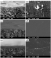
Scanning electron microscopy (SEM) images of cross-sections and surfaces of SiC membranes obtained from different concentrations of coating solutions: (a,b) 1 wt%; (c,d) 3 wt%; and (e,f) 5 wt%. Reprinted from [82] with permission from John Wiley and Sons.
Figure 10
Figure 10
Production process of SiC ceramics under different atmospheres. Adapted from [94] with permission from John Wiley and Sons.
Figure 11
Figure 11
(a) Main structure of AHPCS; (b) schematic illustration of the thermal curing for pre-cross-linking of AHPCS. Reprinted from [73] with permission from Elsevier.
Figure 12
Figure 12
Colloidal size distributions determined by dynamic light scattering for parent AHPCS and pre-cross-linked AHPCS (PCL–AHPCS). The bold lines represent the average of the same sample. Reprinted from [73] with permission from Elsevier.
Figure 13
Figure 13
TG–MS curves of Si-containing preceramic polymers (polytitanocarbosilane) under a He atmosphere with a heating rate of 10 °C/min to a level of 1000 °C. Adapted from [55] with permission from Elsevier.
Figure 14
Figure 14
(a) N2 adsorption–desorption isotherms at 77 K, (b) BET surface area and micropore volume (at a relative pressure of P/P0 = 0.01, pore size ≤ 1 nm) of pyrolyzed precursor (TiPCS) powders. Adapted from [55] with permission from Elsevier.
Figure 15
Figure 15
Schematic of the evolution of the network structure for polymeric precursors (e.g., AHPCS) pyrolyzed at different temperatures. Reprinted from [73] with permission from Elsevier.
Figure 16
Figure 16
Schematic illustration of the conversion reaction of PMS to PCS.
Figure 17
Figure 17
(a) Chemical structures of PCS and PVS; (b) SEM image of the cross-section of PCS/PVS-derived membranes (the inset shows the atomic content curves of Al and Si throughout the sample cross section measured by energy dispersive X-ray spectroscopy; B: α-alumina, C: γ-alumina, D: SiC membrane layer, 1.25 μm) (adapted from [101] with permission from Elsevier).
Figure 18
Figure 18
(a) Permeance and selectivity for H2/C3H8 through PCS-derived membranes as a function of the test time at 500 °C (mixture: 50/50, feed pressure: 250 kPa (abs.), permeate pressure: 100 kPa (abs.)); (b) comparison of separation performance of various types of membranes for H2/C3H8 at 20 °C–650 °C. Adapted from [72] with permission from Elsevier.
Figure 19
Figure 19
Comparison of separation performance of various types of membranes for CO2/CH4 at or around room temperature. Reprinted from [72] with permission from Elsevier.
Figure 20
Figure 20
SEM images of the top surface and cross-section of pre-cross-linked AHPCS-derived membranes: (a) low and (b) high magnification. Reprinted from [73] with permission from Elsevier.
Figure 21
Figure 21
(a) Single-gas permeance at 200 °C for AHPCS-derived membranes pyrolyzed at different temperatures (M700 was derived from the parent AHPCS solution, while M700′ was derived from the pre-cross-linked AHPCS solution); (b) relationship between the gas permeation performance and pyrolysis temperature. Adapted from [73] with permission from Elsevier.
Figure 22
Figure 22
Cross section of a multilayer Si–B–C–N/γ-Al2O3/α-Al2O3 membrane. Adapted from [107] with permission from John Wiley and Sons.
Figure 23
Figure 23
Comparison of the selectivities for (a) H2/N2 and (b) N2/SF6 by various membranes [72,73,82].
Figure 24
Figure 24
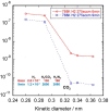
Single-gas permeance at 200 °C as a function of molecular size for a PCS-derived membrane before and after thermal stability testing at 500 °C under a He atmosphere for 12 h. Adapted from [72] with permission from Elsevier.
Figure 25
Figure 25
(a) Single-gas permeance at 200 °C for a PCS-derived membrane before and after air treatment at 500 °C; (b) time-course changes in the weight of PCS-derived SiC powder in air at 500 °C following 12 h. The powder was prepared under the same conditions as the membrane. Adapted from [72] with permission from Elsevier.
Figure 26
Figure 26
Schematic of the iodine–sulfur thermochemical water-splitting cycle. Reprinted from [117] with permission from Elsevier.
Figure 27
Figure 27
(a) Schematic of an experiment for steam and H2SO4 treatment and gas permeation; (b) schematic of the SiC membrane used for H2SO4 decomposition in a membrane reactor at 600 °C. Reprinted from [34] with permission.

References

    1. Logan B.E., Elimelech M. Membrane-based processes for sustainable power generation using water. Nature. 2012;488:313–319. doi: 10.1038/nature11477. - DOI - PubMed
    1. Sholl D.S., Lively R.P. Seven chemical separations to change the world. Nature. 2016;532:435–437. doi: 10.1038/532435a. - DOI - PubMed
    1. Ezugbe E.O., Rathilal S. Membrane Technologies in Wastewater Treatment: A Review. Membranes. 2020;10:89. doi: 10.3390/membranes10050089. - DOI - PMC - PubMed
    1. Voutchkov N. Energy use for membrane seawater desalination—Current status and trends. Desalination. 2018;431:2–14. doi: 10.1016/j.desal.2017.10.033. - DOI
    1. Liang C.Z., Chung T.-S., Lai J.-Y. A review of polymeric composite membranes for gas separation and energy production. Prog. Polym. Sci. 2019;97:101141. doi: 10.1016/j.progpolymsci.2019.06.001. - DOI

LinkOut - more resources