

Vehicle Stability Analysis under Extreme Operating Conditions Based on LQR Control
- PMID: 36560162
- PMCID: PMC9783117
- DOI: 10.3390/s22249791
Vehicle Stability Analysis under Extreme Operating Conditions Based on LQR Control
Abstract
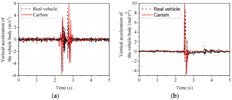
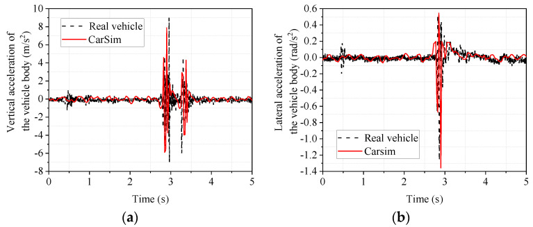
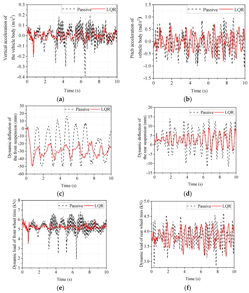
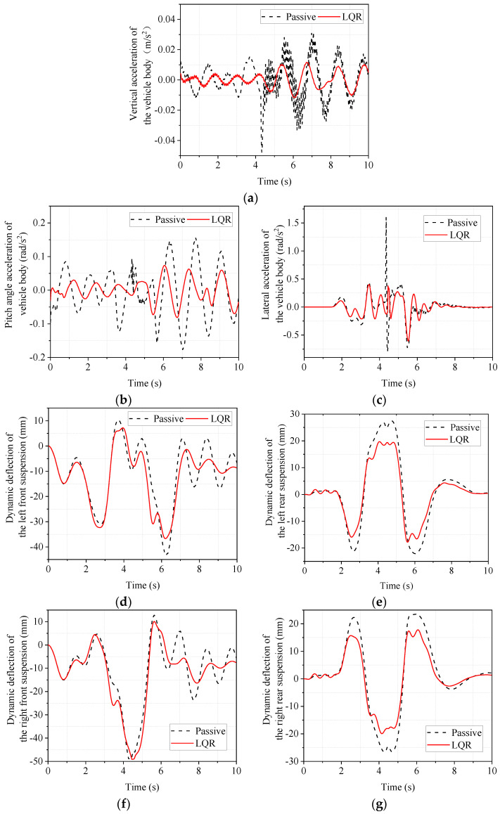
Under extreme working conditions such as high-speed driving on roads with a large road surface unevenness coefficient, turning on a road with a low road surface adhesion coefficient, and emergency acceleration and braking, a vehicle's stability deteriorates sharply and reduces ride comfort. There is extensive existing research on vehicle active suspension control, trajectory tracking, and control methods. However, most of these studies focus on conventional operating conditions, while vehicle stability analysis under extreme operating conditions is much less studied. In order to improve the stability of the whole vehicle under extreme operating conditions, this paper investigates the stability of a vehicle under extreme operating conditions based on linear quadratic regulator (LQR) control. First, a seven degrees of freedom (7-DOF) dynamics model of the whole vehicle is established based on the use of electromagnetic active suspension, and then an LQR controller of the electromagnetic active suspension is designed. A joint simulation platform incorporating MATLAB and CarSim was built, and the CarSim model is verified by real vehicle tests. Finally, the stability of the vehicle under four different ultimate operating conditions was analyzed. The simulation results show that the root mean square (RMS) values of body droop acceleration and pitch angle acceleration are improved by 57.48% and 28.81%, respectively, under high-speed driving conditions on Class C roads. Under the double-shift condition with a low adhesion coefficient, the RMS values of body droop acceleration, pitch acceleration, and roll angle acceleration are improved by 58.25%, 55.41%, and 31.39%, respectively. These results indicate that electromagnetic active suspension can significantly improve vehicle stability and reduce driving risk under extreme working conditions when combined with an LQR controller.
Keywords: CarSim; LQR controller; extreme operating conditions; vehicle stability.
Conflict of interest statement
The authors declare no conflict of interest.
Figures


References
-
- Aljarbouh A., Fayaz M., Qureshi M.S., Boujoudar Y. Hybrid Sliding Mode Control of Full-Car Semi-Active Suspension Systems. Symmetry. 2021;13:2442. doi: 10.3390/sym13122442. - DOI
-
- Nichiţelea T.-C., Unguritu M.-G. Design and comparisons of adaptive harmonic control for a quarter-car active suspension. Proc. Inst. Mech. Eng. Part D J. Automob. Eng. 2021;236:343–352. doi: 10.1177/09544070211019251. - DOI
-
- Beltran-Carbajal F., Valderrabano-Gonzalez A., Favela-Contreras A., Hernandez-Avila J.L., Lopez-Garcia I., Tapia-Olvera R. An Active Vehicle Suspension Control Approach with Electromagnetic and Hydraulic Actuators. Actuators. 2019;8:35. doi: 10.3390/act8020035. - DOI
-
- Deng Y., Gong M., Ni T. Double-channel event-triggered adaptive optimal control of active suspension systems. Nonlinear Dyn. 2022;108:3435–3448. doi: 10.1007/s11071-022-07360-3. - DOI
Grants and funding
- 52005345/National Natural Science Fund of China
- 52005344/National Natural Science Fund of China
- 2020YFC2006701/National Key Research and Development Project
- LFGD2020002/Scientific Research Fund Project of Liaoning Provincial Department of Education
- 2022JH1/10400027/Major Project of the Ministry of Science and Technology of Liaoning Province
LinkOut - more resources
Full Text Sources
