

Effects of stent shape on focal hemodynamics in intracranial atherosclerotic stenosis: A simulation study with computational fluid dynamics modeling
- PMID: 36582612
- PMCID: PMC9792661
- DOI: 10.3389/fneur.2022.1067566
Effects of stent shape on focal hemodynamics in intracranial atherosclerotic stenosis: A simulation study with computational fluid dynamics modeling
Abstract
Background and aims: The shape of a stent could influence focal hemodynamics and subsequently plaque growth or in-stent restenosis in intracranial atherosclerotic stenosis (ICAS). In this preliminary study, we aim to investigate the associations between stent shapes and focal hemodynamics in ICAS, using computational fluid dynamics (CFD) simulations with manually manipulated stents of different shapes.
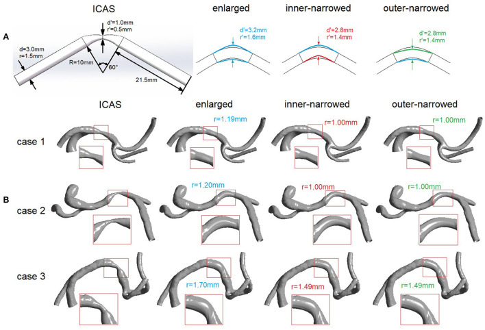
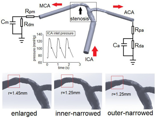
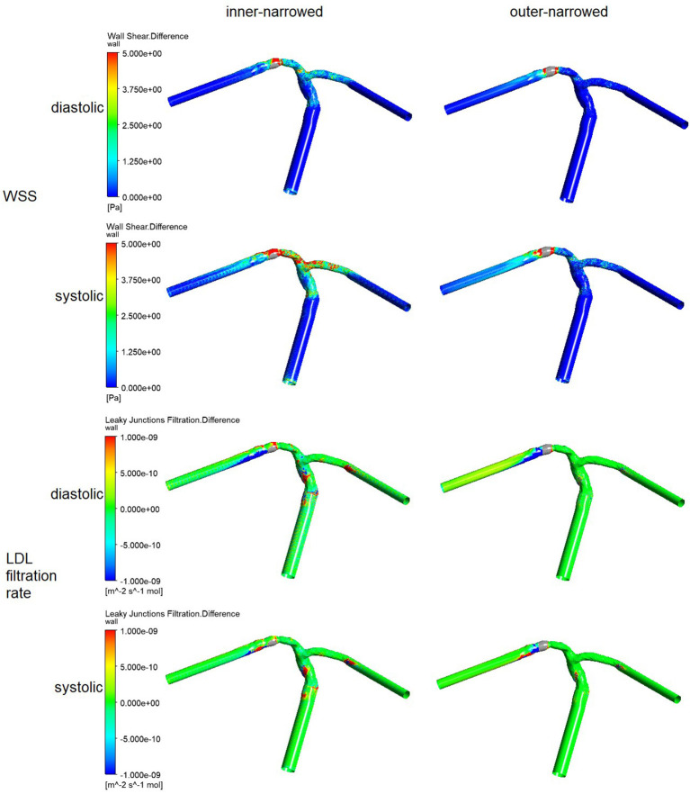
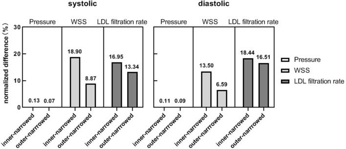
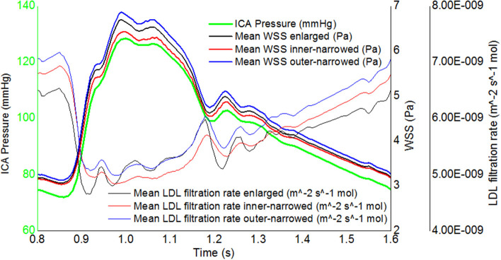
Methods: We built an idealized artery model, and reconstructed four patient-specific models of ICAS. In each model, three variations of stent geometry (i.e., enlarged, inner-narrowed, and outer-narrowed) were developed. We performed static CFD simulation on the idealized model and three patient-specific models, and transient CFD simulation of three cardiac cycles on one patient-specific model. Pressure, wall shear stress (WSS), and low-density lipoprotein (LDL) filtration rate were quantified in the CFD models, and compared between models with an inner- or outer-narrowed stent vs. an enlarged stent. The absolute difference in each hemodynamic parameter was obtained by subtracting values from two models; a normalized difference (ND) was calculated as the ratio of the absolute difference and the value in the enlarged stent model, both area-averaged throughout the arterial wall.
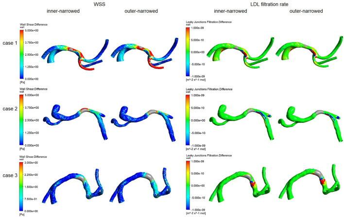
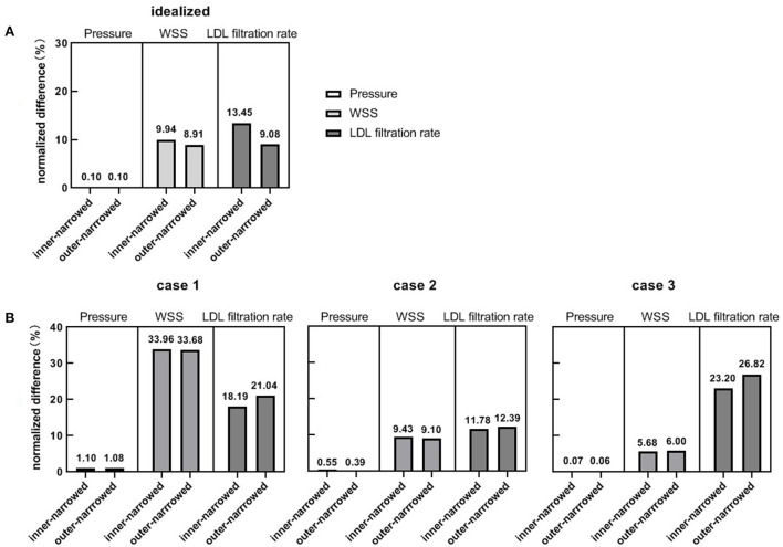
Results: The differences in focal pressure in models with different stent geometry were negligible (ND<1% for all cases). However, there were significant differences in the WSS and LDL filtration rate with different stent geometry, with ND >20% in a static model. Observable differences in WSS and LDL filtration rate mainly appeared in area adjacent to and immediately distal to the stent. In the transient simulation, the LDL filtration rate had milder temporal fluctuations than WSS.
Conclusions: The stent geometry might influence the focal WSS and LDL filtration rate in ICAS, with negligible effect on pressure. Future studies are warranted to verify the relevance of the changes in these hemodynamic parameters in governing plaque growth and possibly in-stent restenosis in ICAS.
Keywords: computational fluid dynamics (CFD); hemodynamics; in-stent restenosis (ISR); intracranial atherosclerotic stenosis (ICAS); low-density lipoprotein (LDL); stent geometry; wall shear stress (WSS).
Copyright © 2022 Liu, Liu, Ip, Ma, Abrigo, Soo, Leung and Leng.
Conflict of interest statement
The authors declare that the research was conducted in the absence of any commercial or financial relationships that could be construed as a potential conflict of interest.
Figures
Similar articles
-
Comparison of Newtonian and Non-newtonian Fluid Models in Blood Flow Simulation in Patients With Intracranial Arterial Stenosis.Front Physiol. 2021 Sep 6;12:718540. doi: 10.3389/fphys.2021.718540. eCollection 2021. Front Physiol. 2021. PMID: 34552505 Free PMC article.
-
Alterations in regional vascular geometry produced by theoretical stent implantation influence distributions of wall shear stress: analysis of a curved coronary artery using 3D computational fluid dynamics modeling.Biomed Eng Online. 2006 Jun 16;5:40. doi: 10.1186/1475-925X-5-40. Biomed Eng Online. 2006. PMID: 16780592 Free PMC article.
-
Coronary arteries hemodynamics: effect of arterial geometry on hemodynamic parameters causing atherosclerosis.Med Biol Eng Comput. 2020 Aug;58(8):1831-1843. doi: 10.1007/s11517-020-02185-x. Epub 2020 Jun 9. Med Biol Eng Comput. 2020. PMID: 32519006
-
Clinical implications of haemodynamics in symptomatic intracranial atherosclerotic stenosis by computational fluid dynamics modelling: a systematic review.Stroke Vasc Neurol. 2025 Feb 25;10(1):16-24. doi: 10.1136/svn-2024-003202. Stroke Vasc Neurol. 2025. PMID: 38806205 Free PMC article.
-
Relationship Between Coronary Fractional Flow Reserve and Computational Fluid Dynamics Analysis in Moderate Stenosis of the Coronary Artery.Circ Rep. 2020 Sep 25;2(10):545-551. doi: 10.1253/circrep.CR-20-0078. Circ Rep. 2020. PMID: 33693179 Free PMC article. Review.
Cited by
-
Geometric consistency among atherosclerotic plaques in carotid arteries evaluated by multidimensional parameters.Heliyon. 2024 Sep 6;10(18):e37419. doi: 10.1016/j.heliyon.2024.e37419. eCollection 2024 Sep 30. Heliyon. 2024. PMID: 39309847 Free PMC article.
-
A case report of effective treatment of intracranial atherosclerotic stenosis treated with the integration of traditional Chinese medicine and Western medicine.Medicine (Baltimore). 2024 Oct 11;103(41):e40055. doi: 10.1097/MD.0000000000040055. Medicine (Baltimore). 2024. PMID: 39465829 Free PMC article.
-
Comparative analysis of RADAR vs. conventional techniques for AVF maturation in patients with blood viscosity and vessel elasticity-related diseases through fluid-structure interaction modeling: Anemia, hypertension, and diabetes.PLoS One. 2024 Jan 16;19(1):e0296631. doi: 10.1371/journal.pone.0296631. eCollection 2024. PLoS One. 2024. PMID: 38227602 Free PMC article.
-
Panvascular concept in the evaluation and treatment of intracranial atherosclerotic stenosis.Front Neurol. 2024 Dec 24;15:1460124. doi: 10.3389/fneur.2024.1460124. eCollection 2024. Front Neurol. 2024. PMID: 39777318 Free PMC article. Review.
-
A non-linear relationship between lesion length and risk of recurrent cerebral ischemia after stenting for symptomatic intracranial stenosis with hemodynamic impairment.Front Neurol. 2023 Apr 18;14:1122708. doi: 10.3389/fneur.2023.1122708. eCollection 2023. Front Neurol. 2023. PMID: 37143995 Free PMC article.
References
LinkOut - more resources
Full Text Sources
Research Materials
Miscellaneous