Review
. 2023 Mar;10(7):e2204072.
doi: 10.1002/advs.202204072. Epub 2022 Dec 30.

Two-Photon Polymerization: Fundamentals, Materials, and Chemical Modification Strategies

Affiliations
Review

Two-Photon Polymerization: Fundamentals, Materials, and Chemical Modification Strategies

Seán O'Halloran et al. Adv Sci (Weinh). 2023 Mar.

Abstract

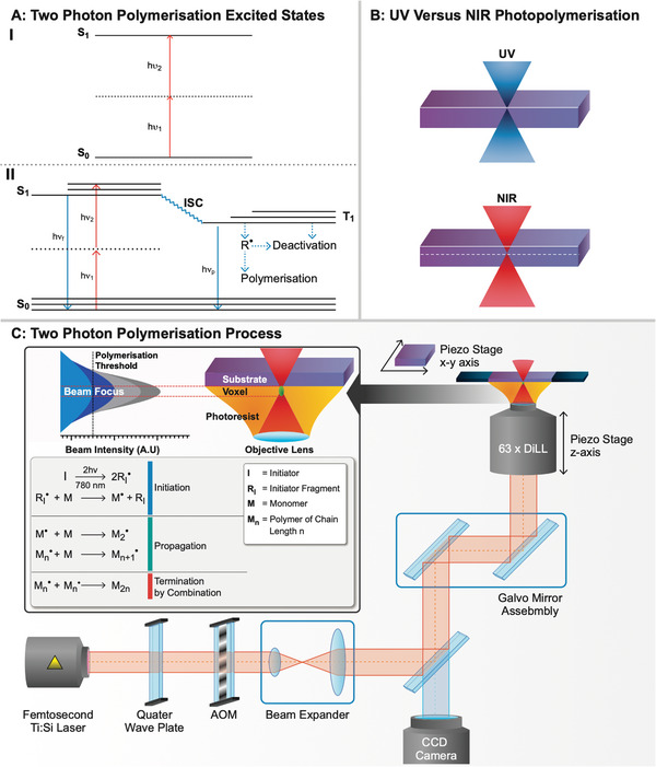
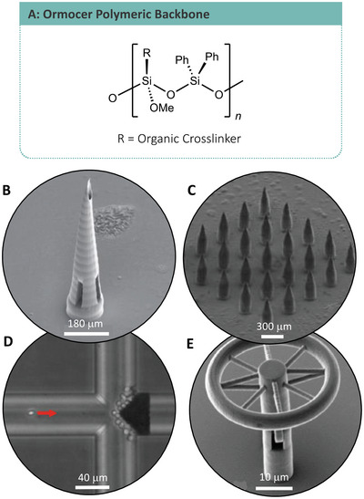
Two-photon polymerization (TPP) has become a premier state-of-the-art method for microscale fabrication of bespoke polymeric devices and surfaces. With applications ranging from the production of optical, drug delivery, tissue engineering, and microfluidic devices, TPP has grown immensely in the past two decades. Significantly, the field has expanded from standard acrylate- and epoxy-based photoresists to custom formulated monomers designed to change the hydrophilicity, surface chemistry, mechanical properties, and more of the resulting structures. This review explains the essentials of TPP, from its initial conception through to standard operating principles and advanced chemical modification strategies for TPP materials. At the outset, the fundamental chemistries of radical and cationic polymerization are described, along with strategies used to tailor mechanical and functional properties. This review then describes TPP systems and introduces an array of commonly used photoresists including hard polyacrylic resins, soft hydrogel acrylic esters, epoxides, and organic/inorganic hybrid materials. Specific examples of each class-including chemically modified photoresists-are described to inform the understanding of their applications to the fields of tissue-engineering scaffolds, micromedical, optical, and drug delivery devices.

Keywords: 3D laser printing; direct laser writing; modification strategies; photoresists; two-photon polymerization.


Conflict of interest statement

The authors declare no conflict of interest.

Figures

Figure 1
Figure 1
A) (I) Type I, self‐cleaving photoinitiator azo‐bisisobutyronitrile. (II) Type II, acid catalyzed photoinitiator benzophenone. B) Formation of the initiating ion pair Lewis acid from the reaction of trihalogen containing compounds with hydroxyl‐containing compounds. C) High TPA cross‐section photoinitiators: i) B3FL and ii) R1.
Figure 2
Figure 2
Radical polymerization: The initiation and initial propagation of radical polymerizations using AIBN and acrylic monomers, with SEM imaging of TPP produced neuronal cell scaffold using IP‐DIP photoresist from Nanoscribe (cf. Section 4.1.3). Reprinted (adapted) with permission.[ 62 ] Copyright 2022, American Chemical Society. Cationic polymerization: The initiation and initial propagation steps of cationic polymerizations utilizing aluminum trichloride Lewis acid and epoxide monomers, with SEM imaging of TPP produced using epoxide doped resin (cf. Section 4.4.1). Adapted with permission.[ 108 ] Copyright 2022, Springer Nature.
Figure 3
Figure 3
A) (I) Two‐photon absorption leading to the excitation of an electron to an excited state through a simultaneous absorption and a virtual, short‐lived intermediate state. (II) Initiation of the TPP process, displaying the competing processes to radical generation (R•), through emissive (solid blue line) fluorescence (f ) and phosphorescence (p ) and nonemissive (dashed blue line) routes. (Adapted from Sun and Kawata) B) (I) UV photopolymerization displaying low penetration and high surface interaction with a photopolymerizable material. (II) NIR photopolymerization displaying minimal surface interaction and increased penetration when compared with UV. C) TPP system setup for printing in dip‐in laser lithography (DiLL) mode.
Figure 4
Figure 4
A) Core acrylic functionality. B) Acrylic polymer backbone. C) Acrylic microneedle. Adapted with permission.[ 53 ] Copyright 2022, Elsevier. D) Microfiber optic tapers for beam expansion. Adapted with permission.[ 55 ] Copyright 2022, Elsevier. E) Micro aerosolizer. Adapted with permission.[ 59 ] Copyright 2022, Institute of Electrical and Electronics Engineers. F) Cell scaffolding for neuronal networks. Adapted with permission.[ 62 ] Copyright 2022, American Chemical Society. G) Acrylic cell scaffolding. Adapted with permission.[ 61 ] Copyright 2022, Wiley.
Figure 5
Figure 5
Illustration of micro‐optics constructed using IP‐S acrylate‐based resin. A) Proposed design of doublet micro‐optic. B) SEM image of doublet lens printed with 90° section to display internal lens doublet. C) Simulated image of the resolution test chart. D) Resolution test chart observed using doublet lens printed using IP‐S. E) IP‐S triplet micro‐optic arrested on the end of a microfiber optic cable suspended in a needle. Illustrations generated from ref. [56].
Figure 6
Figure 6
A) Physical interaction between peptide backbone of gelatin type hydrogels, hydrogen bonds between amine and carboxylate groups. B) Chemical interactions of a hydrogel consisting of PEG‐DA oligomers with n number of repeating glycol units. C–G) Examples of hydrogel cell scaffolding. SEM images adapted with permission. (C)–(G) Adapted with permission.[ 69 ] Copyright 2022, American Chemical Society; Adapted with permission.[ 64 ] Copyright 2022, IOP Publishing; Adapted with permission.[ 79 ] Copyright 2022, Elsevier; Adapted with permission.[ 76 ] Copyright 2022, American Chemical Society; Apadted with permission.[ 78 ] Copyright 2022, Multidisciplinary Digital Publishing Institute.
Figure 7
Figure 7
A) Cell scaffold constructed using PEG‐DA based hydrogel. B,C) Scaffold decorated with Ormocomp blocks for cell‐specific binding. Reproduced with permission.[ 52 ] Copyright 2022, Wiley.
Figure 8
Figure 8
SEM images: A) Organic/inorganic hybrid backbone of ORMOCER polymers. B) Ormocer microneedle. Adapted with permission.[ 87 ] Copyright 2022, American Scientific Publishers. C) Microneedle array. Adapted with permission.[ 72 ] Copyright 2022, IOP Publishing. D) Microfilter for blood plasma separations. Adapted with permission.[ 103 ] Copyright 2022, Royal Society of Chemistry. E) Optical microresonator for studying light matter interactions. Adapted with permission.[ 104 ] Copyright 2022, Optica Publishing Group.
Figure 9
Figure 9
A) Core epoxide monomer functionality. B) Epoxide polymer backbone. Helical microswimmers constructed using SU‐8 epoxide‐based photoresist and IP‐L acrylate‐based resist. C) Construction methodology involving TPP followed nickel/titanium coating. D) An array of helical microswimmers. E) Vertically printed SU‐8 microswimmer. F+G) Close‐up of shadowing on the substrate arising due to the evaporation process associated with the coating process. H) Microswimmer functionalized with a holder for carrying microparticles. (C)–(H) Reproduced with permission.[ 107 ] Copyright 2022, Wiley.
Figure 10
Figure 10
Photoinduced, chemical modification and resin additive methods for the functionalization of polymeric surfaces and materials.

Similar articles

Cited by

References

    1. Nesvadba P., in Encyclopedia of Radicals in Chemistry, Biology and Materials (Eds: Chatgilialoglu C., Studer A.), Wiley, Chichester, UK: 2012.
    1. Destarac M., Polym. Chem. 2018, 9, 4947.
    1. Hawker C. J., J. Am. Chem. Soc. 1994, 116, 11185.
    1. Hawker C. J., Bosman A. W., Harth E., Chem. Rev. 2001, 101, 3661. - PubMed
    1. Grubbs R. B., Grubbs R. H., Macromolecules 2017, 50, 6979.

LinkOut - more resources