Review
. 2022 Nov 17;13(12):6508-6532.
doi: 10.1364/BOE.473458. eCollection 2022 Dec 1.

Adaptive optics visual simulators: a review of recent optical designs and applications [Invited]

Affiliations
Review

Adaptive optics visual simulators: a review of recent optical designs and applications [Invited]

Susana Marcos et al. Biomed Opt Express. .

Abstract

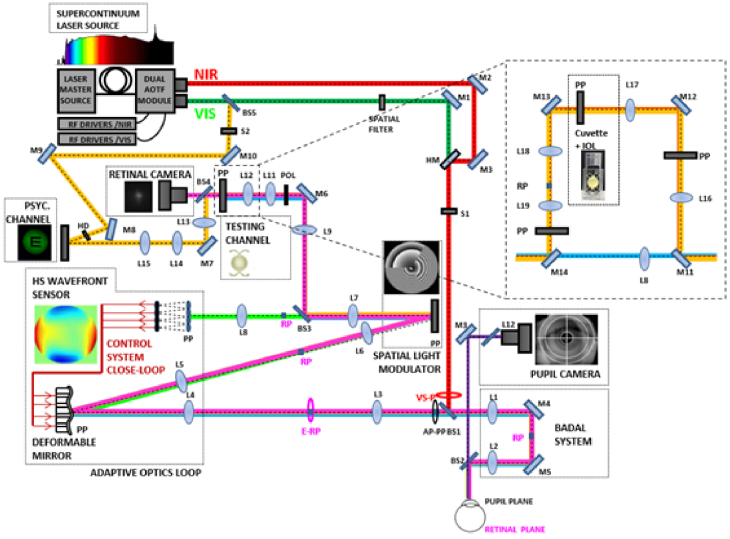
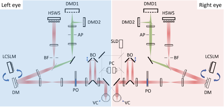
In their pioneering work demonstrating measurement and full correction of the eye's optical aberrations, Liang, Williams and Miller, [JOSA A14, 2884 (1997)10.1364/JOSAA.14.002884] showed improvement in visual performance using adaptive optics (AO). Since then, AO visual simulators have been developed to explore the spatial limits to human vision and as platforms to test non-invasively optical corrections for presbyopia, myopia, or corneal irregularities. These applications have allowed new psychophysics bypassing the optics of the eye, ranging from studying the impact of the interactions of monochromatic and chromatic aberrations on vision to neural adaptation. Other applications address new paradigms of lens designs and corrections of ocular errors. The current paper describes a series of AO visual simulators developed in laboratories around the world, key applications, and current trends and challenges. As the field moves into its second quarter century, new available technologies and a solid reception by the clinical community promise a vigorous and expanding use of AO simulation in years to come.


Conflict of interest statement

SM discloses funding from Alcon Research Labs (CSIC), BVI-PhysIOL (CSIC), ClerioVision (UoR) Coopervision (CSIC, UoR), Essilor International (CSIC), Johnson and Johnson (CSIC), Staar Surgical (CSIC), Meta Reality Labs (UoR), Hoya (CSIC) for research with the described instruments. SM is a co-founder, shareholder and board member of 2EyesVision SL, a spin-off company of CSIC, which licenses related Vision Simulator technologies and is a co-inventor of patents P201730854, US9693679 and US10213358 licensed to 2EyesVision; SM is co-inventor of patent US10226327 and P201930791 (PhysIOL) and US2018042474 (Essilor) that used the described AO technology in their development. PA is a co-founder of Voptica SL, a start-up of the University of Murcia and co-inventor of patents US20120154742 and US20120038884 licensed to Voptica. DA discloses support by Carl Zeiss Vision. RL discloses funding from Essilor International. LL discloses support from Johnson and Johnson where the AO system was used. GY discloses support from Bausch and Lomb, Johnson and Johnson, and Alcon.

Figures

Fig. 1.
Fig. 1.
Schematic diagram of the latest version of the VioBio Lab AOII system [8]. Label abbreviations: M stands for Mirrors, L for Lenses, BS for Beam Splitters, HM for hot mirror,, POL polarizer, HD for high-density filter. RP are retinal planes; PP are pupil planes.
Fig. 2.
Fig. 2.
A. MTF radial profiles calculated from the measured wave aberrations for two patients (maps on top of each graph with natural HOAs and AO-corrected HOAs). Solid lines stand for AO-corrected HOAs, and dashed lines for natural HOAs. Green lines are for 555 nm at best focus. Blue lines are for 480 nm (including chromatic defocus). B. Illustration of images presented in the psychophysical score experiment through natural and AO corrected aberrations. Green images are presented in focus and out of focus (defocus equivalent to green-blue chromatic blur). Blue images are naturally defocused, as the best focus is set for green. C. Perceived Image quality score and Optical Visual Strehl Ratios AO/NoAO (upper graph), for green (in focus) and blue (defocused by chromatic defocus). Correcting HOAs improves the optics by a factor 2, and very moderately perceived image quality in green; and degrades the optics and perceived image quality (upper graph) in blue; Perceived image quality score on defocused green images (equivalent chromatic defocus) and in blue (naturally defocused) (bottom graph). Blue images are consistently scored higher than defocused green images) for both AO and noAO. Data are average of 10 patients, and for 6-mm pupils, adapted from [33], where individual data are presented.
Fig. 3.
Fig. 3.
SLM-based simulations of commercial center distance low, medium and high add contact lenses for presbyopia. A. Phase-wrapped phase maps of the three contact lens designs, as mapped on the SLM. B. Through Focus Visual Acuity with the real multifocal contact lenses on the eye (Top) and the SLM-simulated Contact lenses (Bottom). C. Difference between Simulation and Real CL (logMAR) as a function of defocus; (D) Shape similarity metric (correlation) between SLM and Real MCL on the eye. The figure illustrates an example of an individual eye (S7) from the Vedhakrishnan et al. study [44].
Fig. 4.
Fig. 4.
A. Schematic of the Murcia AO visual simulators: A. AO system with amplitude and phase control for the simultaneous generation and compensation of the effects of intraocular scattering with WS. B. Binocular AO visual simulator. Label abbreviations: FM stands for flip mirror, M for mirror, RD for rotating diffuser, BS for beam splitter, CA for circular aperture, POL, linear polarizer, IR LED for infrared light-emitting diode, LC for liquid crystal, SLM for Spatial Light Modulator, EMCCD for electro-multiplying charged-coupled device, FPC and LPC for frontal and lateral pupil cameras. The red dotted line depicts the path of the beam during the feedback based WS correction
Fig. 5.
Fig. 5.
Schematic diagram of the adaptive optics setup used to correct on-axis and peripheral aberration. LD - Red laser diode (λ = 635 nm), L1 to 8 - achromatic lenses, S1 to 4 - apertures (S1 - Laser diode luminance controller, S2 - corneal reflection controller, S3 - stop, S4 - field size controller), M1 - plane mirror, BS1 to 3 - beam splitter, TL - + 2D or –2D trial lens to induce defocus, FT - peripheral fixation LED targets (+20°), DM - ALPAO DM69-15 deformable mirror, HSWS - Hartmann-Shack wavefront sensor, F1 - Monochromatic filter (λ = 532 nm), P – pupil/pupil conjugate plane, R – retina/retinal conjugate plane.
Fig. 6.
Fig. 6.
Measured and predicted peripheral contrast sensitivity functions for one participant with vertical grating orientation: in-focus and with +2 D and −2D blur induced by trial lenses. Error bars represent the standard deviations for three repetitions. Error bars are not visible when the standard deviation is less than 0.05 log contrast sensitivity. Log contrast sensitivity is shown down to −0.5 to better show the pattern of predicted values, although the shaded region below 0 (where there is 100% contrast) cannot occur physically. Arrows indicate measured +2 D (red), measured −2D (blue), and predicted (black) spatial frequencies of notches. Adapted from Jaisankar et al. [78].
Fig. 7.
Fig. 7.
Schematic diagram of the dual wavefront sensing channel monocular adaptive optics system. L, lens, (focal length in millimeters); PM, plane mirror; OAPM, off-axis parabolic mirror; A, aperture; PBS and CBS, pellicle and cube beamsplitter respectively (transmission: reflection).
Fig. 8.
Fig. 8.
Accommodation responses to a step change in stimulus demand for a single subject when all aberrations from second order (excluding defocus) up to and including sixth radial order are inverted following the stimulus step change [84]. An example of a correct and incorrect accommodative response is shown.
Fig. 9.
Fig. 9.
Schematic diagram of the crx1 device.
Fig. 10.
Fig. 10.
Schematic diagram of the two methods used to compare real and simulated optical blur.
Fig. 11.
Fig. 11.
Schematic diagram of the optical set-up of the KTH Adaptive Optics Visual Simulator. TL Trial lens holder, LD Laser Diode 830 nm; L1-7 achromatic lenses; HS Hartmann-Shack sensor; BS1-3 Beamsplitters (1 and 3 are hot mirrors; 2 is a pellicle); A Aperture; Cam Pupil camera.
Fig. 12.
Fig. 12.
The monochromatic modulation transfer function (MTF) and contrast sensitivity (CS) with adaptive optics (AO) versus refractive correction for one subject in the 20° nasal visual field. The left and right columns show the results for gratings orientated perpendicularly to and parallel to the field angle, respectively. The solid lines represent the best image quality in green light, whereas the dashed lines are with monochromatic and chromatic aberrations still affecting the retinal image. Data from Venkataraman et al. [111].
Fig. 13.
Fig. 13.
Schematic optical layout of University of Houston Binocular Adaptive Optics Visual Simulator. DM: Deformable Mirror, LCSLM: Liquid Crystal Spatial Light Modulator, HSWS: Hartmann-Shack Wavefront Sensor, SLD: Superluminescent Laser Diode, DMD: Digital Micromirror Device, VC: Vergence Control, BD: Badal Optometer, PC: Pupil Camera, PO: Phoropter, AP: Artificial Pupil, BF: Binocular Fusion lock
Fig. 14.
Fig. 14.
Effects of long-term neural adaptation on neural functions (A. visual acuity, B. contrast sensitivity) after full AO correction of the eye’s aberrations in normal and keratoconus subjects, and C. stereo threshold as a function of inter-ocular difference in native optical quality. Different symbols represent data from different participants.

References

    1. Liang J., Williams D. R., Miller D. T., “Supernormal vision and high-resolution retinal imaging through adaptive optics,” J. Opt. Soc. Am. A 14(11), 2884–2892 (1997). 10.1364/JOSAA.14.002884 - DOI - PubMed
    1. Campbell F. W., Green D. G., “Optical and retinal factors affecting visual resolution,” J. Physiol. 181(3), 576–593 (1965). 10.1113/jphysiol.1965.sp007784 - DOI - PMC - PubMed
    1. Williams D., Yoon G., Porter J., Guirao A., Hofer H., Cox I., “Visual benefit of correcting higher order aberrations of the eye,” J. Refract. Surg. 16(5), S554–S559 (2000). 10.3928/1081-597X-20000901-12 - DOI - PubMed
    1. Yoon G. Y., Williams D. R., “Visual performance after correcting the monochromatic and chromatic aberrations of the eye,” J. Opt. Soc. Am. A 19(2), 266–275 (2002). 10.1364/JOSAA.19.000266 - DOI - PubMed
    1. Fernandez E. J., Manzanera S., Piers P., Artal P., “Adaptive optics visual simulator,” J. Refract. Surg. 18(5), S634–S638 (2002). 10.3928/1081-597X-20020901-27 - DOI - PubMed

LinkOut - more resources