

Quantum mechanical analysis of excitation energy transfer couplings in photosystem II
- PMID: 36609140
- PMCID: PMC9941724
- DOI: 10.1016/j.bpj.2023.01.002
Quantum mechanical analysis of excitation energy transfer couplings in photosystem II
Abstract
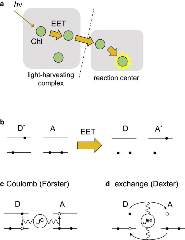
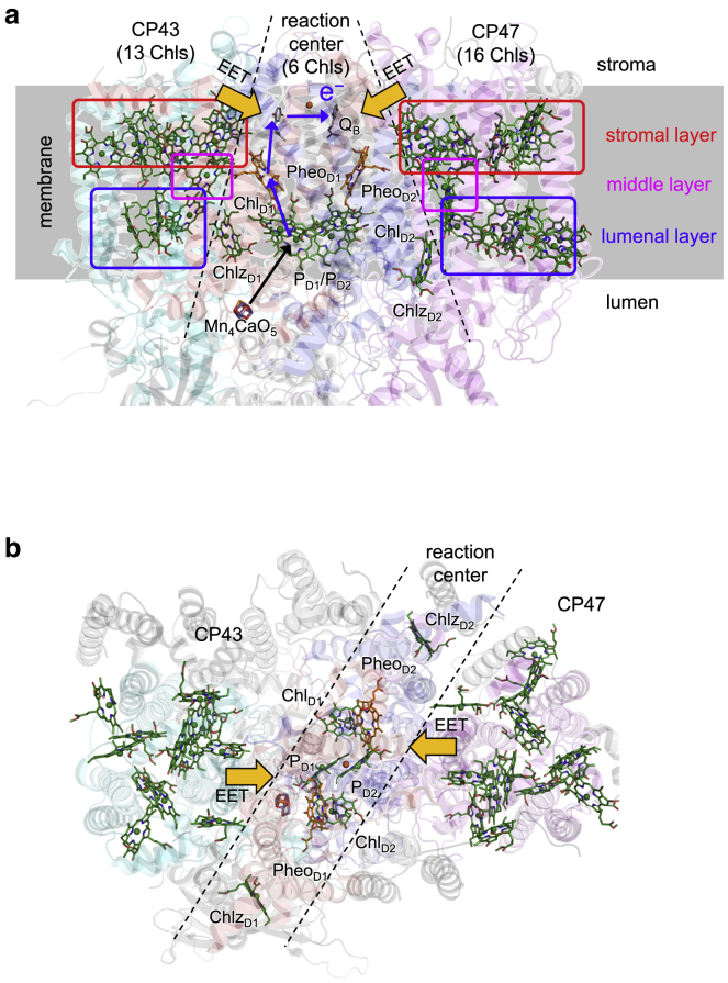
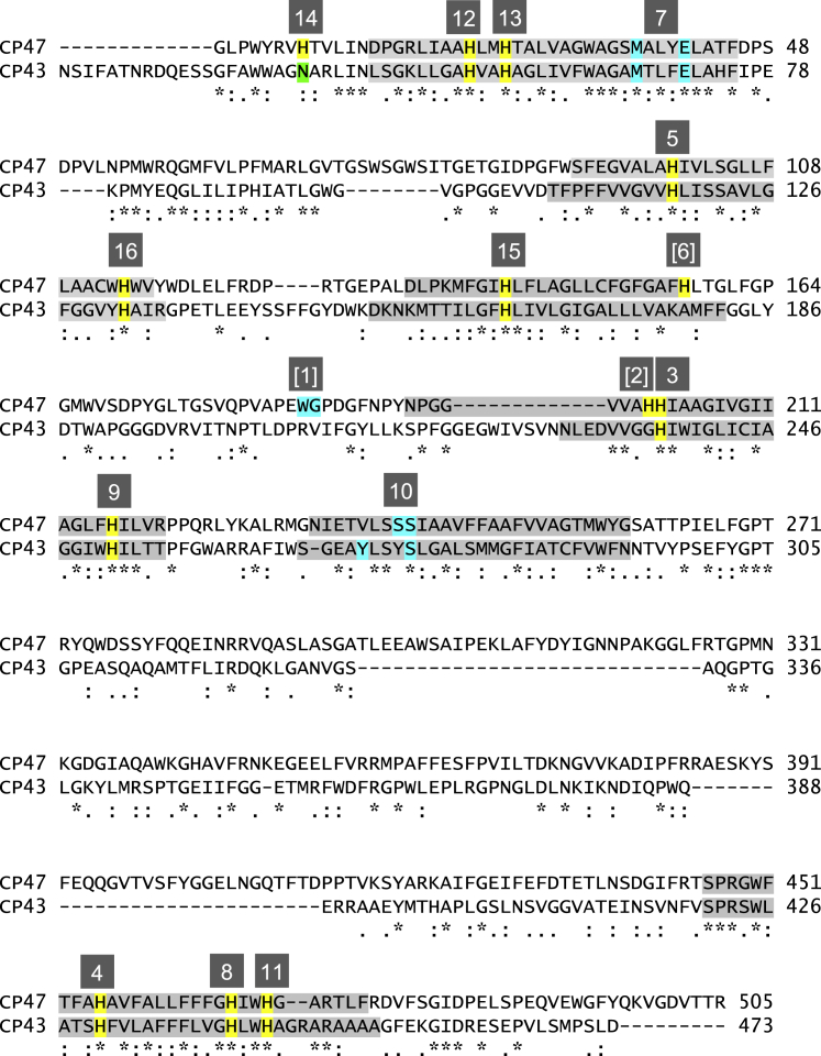
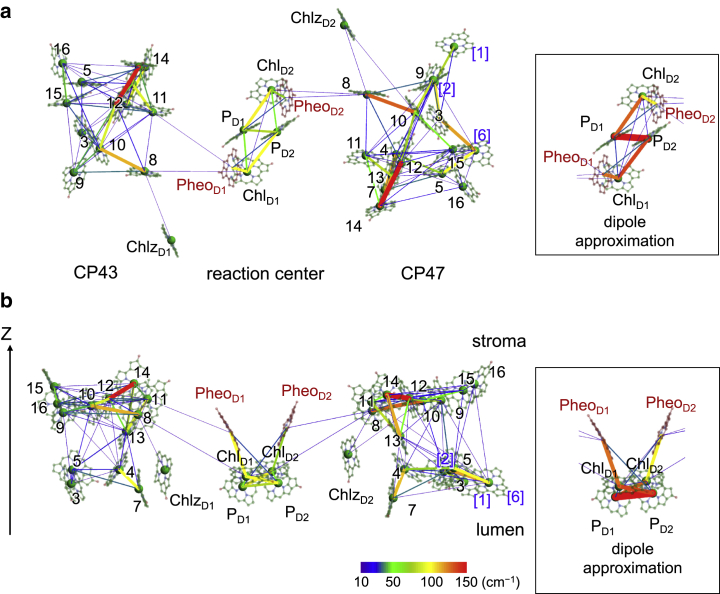
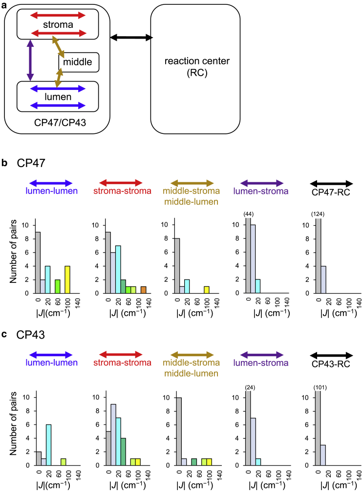
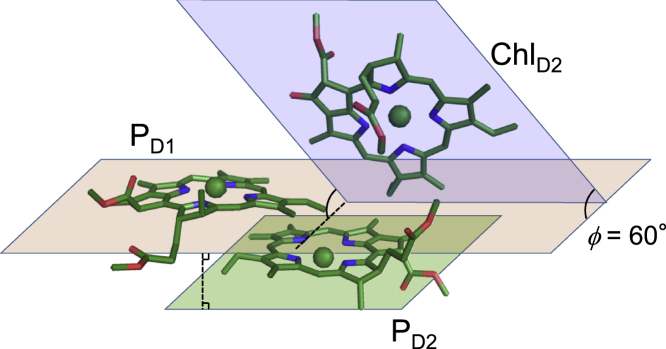
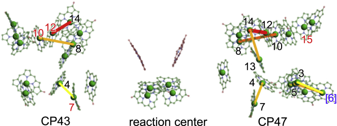
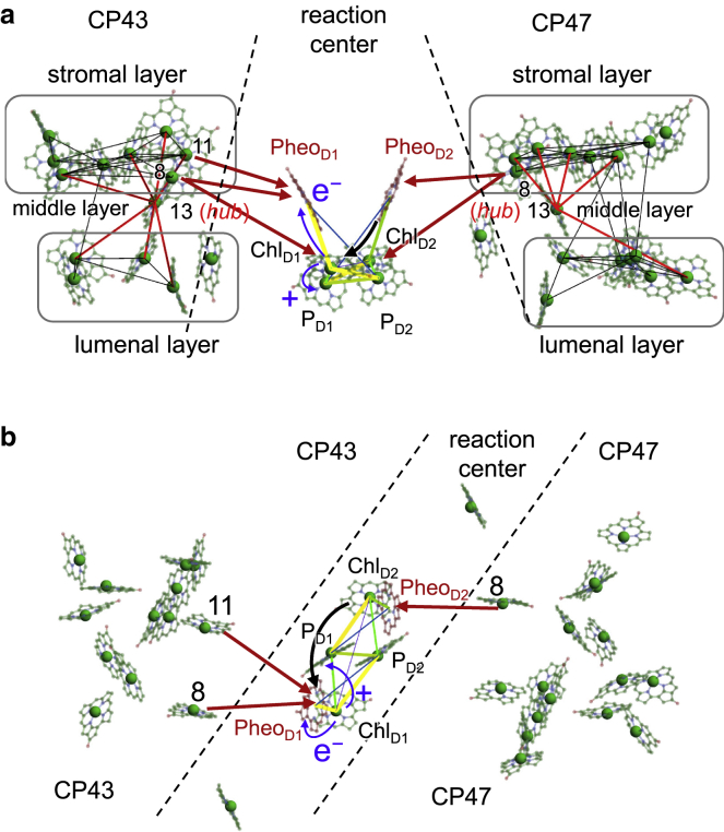
We evaluated excitation energy transfer (EET) coupling (J) between all pairs of chlorophylls (Chls) and pheophytins (Pheos) in the protein environment of photosystem II based on the time-dependent density functional theory with a quantum mechanical/molecular mechanics approach. In the reaction center, the EET coupling between Chls PD1 and PD2 is weaker (|J(PD1/PD2)| = 79 cm-1), irrespective of a short edge-to-edge distance of 3.6 Å (Mg-to-Mg distance of 8.1 Å), than the couplings between PD1 and the accessory ChlD1 (|J(PD1/ChlD2)| = 104 cm-1) and between PD2 and ChlD2 (|J(PD2/ChlD1)| = 101 cm-1), suggesting that PD1 and PD2 are two monomeric Chls rather than a "special pair". There exist strongly coupled Chl pairs (|J| > ∼100 cm-1) in the CP47 and CP43 core antennas, which may be candidates for the red-shifted Chls observed in spectroscopic studies. In CP47 and CP43, Chls ligated to CP47-His26 and CP43-His56, which are located in the middle layer of the thylakoid membrane, play a role in the "hub" that mediates the EET from the lumenal to stromal layers. In the stromal layer, Chls ligated to CP47-His466, CP43-His441, and CP43-His444 mediate the EET from CP47 to ChlD2/PheoD2 and from CP43 to ChlD1/PheoD1 in the reaction center. Thus, the excitation energy from both CP47 and CP43 can always be utilized for the charge-separation reaction in the reaction center.
Copyright © 2023 Biophysical Society. Published by Elsevier Inc. All rights reserved.
Conflict of interest statement
Declaration of interests The authors declare no competing interests.
Figures
Similar articles
-
Charge separation and energy transfer in the photosystem II core complex studied by femtosecond midinfrared spectroscopy.Biophys J. 2007 Oct 15;93(8):2732-42. doi: 10.1529/biophysj.107.105452. Epub 2007 Jun 15. Biophys J. 2007. PMID: 17573421 Free PMC article.
-
Protein Matrix Control of Reaction Center Excitation in Photosystem II.J Am Chem Soc. 2020 Oct 21;142(42):18174-18190. doi: 10.1021/jacs.0c08526. Epub 2020 Oct 9. J Am Chem Soc. 2020. PMID: 33034453 Free PMC article.
-
Light harvesting in photosystem II core complexes is limited by the transfer to the trap: can the core complex turn into a photoprotective mode?J Am Chem Soc. 2008 Apr 2;130(13):4431-46. doi: 10.1021/ja7099826. Epub 2008 Mar 8. J Am Chem Soc. 2008. PMID: 18327941
-
Primary photophysical processes in photosystem II: bridging the gap between crystal structure and optical spectra.Chemphyschem. 2010 Apr 26;11(6):1141-53. doi: 10.1002/cphc.200900932. Chemphyschem. 2010. PMID: 20394099 Review.
-
Revealing the structure of the photosystem II chlorophyll binding proteins, CP43 and CP47.Biochim Biophys Acta. 2000 Aug 15;1459(2-3):239-47. doi: 10.1016/s0005-2728(00)00158-4. Biochim Biophys Acta. 2000. PMID: 11004436 Review.
Cited by
-
Excitation landscape of the CP43 photosynthetic antenna complex from multiscale simulations.Chem Sci. 2024 Apr 9;15(19):7269-7284. doi: 10.1039/d3sc06714a. eCollection 2024 May 15. Chem Sci. 2024. PMID: 38756808 Free PMC article.
-
Superexchange Electron Transfer and Protein Matrix in the Charge-Separation Process of Photosynthetic Reaction Centers.J Phys Chem Lett. 2024 Sep 12;15(36):9183-9192. doi: 10.1021/acs.jpclett.4c02232. Epub 2024 Aug 30. J Phys Chem Lett. 2024. PMID: 39213497
-
Microscopic basis of reaction center modulation in PsbA variants of photosystem II.Proc Natl Acad Sci U S A. 2025 May 20;122(20):e2417963122. doi: 10.1073/pnas.2417963122. Epub 2025 May 12. Proc Natl Acad Sci U S A. 2025. PMID: 40354529 Free PMC article.
References
-
- Scholes G.D. Long-range resonance energy transfer in molecular systems. Annu. Rev. Phys. Chem. 2003;54:57–87. - PubMed
-
- You Z., Hsu C. Theory and calculation for the electronic coupling in excitation energy transfer. Int. J. Quantum Chem. 2014;114:102–115.
-
- Yokono M., Akimoto S. Energy transfer and distribution in photosystem super/megacomplexes of plants. Curr. Opin. Biotechnol. 2018;54:50–56. - PubMed
-
- Damjanović A., Ritz T., Schulten K. Energy transfer between carotenoids and bacteriochlorophylls in light-harvesting complex II of purple bacteria. Phys. Rev. E. 1999;59:3293–3311.
-
- Förster T. Zwischenmolekulare Energiewanderung und Fluoreszenz. Ann. Phys. 1948;437:55–75.
Publication types
MeSH terms
Substances
LinkOut - more resources
Full Text Sources
