Review
. 2022 Dec 23;15(1):65.
doi: 10.3390/polym15010065.

Electrospun Polymer Nanofibers: Processing, Properties, and Applications

Affiliations
Review

Electrospun Polymer Nanofibers: Processing, Properties, and Applications

Abdulhamid Al-Abduljabbar et al. Polymers (Basel). .

Abstract

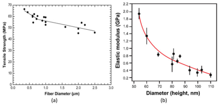
Electrospun polymer nanofibers (EPNF) constitute one of the most important nanomaterials with diverse applications. An overall review of EPNF is presented here, starting with an introduction to the most attractive features of these materials, which include the high aspect ratio and area to volume ratio as well as excellent processability through various production techniques. A review of these techniques is featured with a focus on electrospinning, which is the most widely used, with a detailed description and different types of the process. Polymers used in electrospinning are also reviewed with the solvent effect highlighted, followed by a discussion of the parameters of the electrospinning process. The mechanical properties of EPNF are discussed in detail with a focus on tests and techniques used for determining them, followed by a section for other properties including electrical, chemical, and optical properties. The final section is dedicated to the most important applications for EPNF, which constitute the driver for the relentless pursuit of their continuous development and improvement. These applications include biomedical application such as tissue engineering, wound healing and dressing, and drug delivery systems. In addition, sensors and biosensors applications, air filtration, defense applications, and energy devices are reviewed. A brief conclusion is presented at the end with the most important findings and directions for future research.

Keywords: biomedical application; composite materials functional nanofiber; electrospinning; energy storage separation; mechanical properties; polymer nanofibers; polymer processing.


Conflict of interest statement

The authors declare no conflict of interest.

Figures

Figure 1
Figure 1
A typical plot of stress–strain relationship for nylon-6 nanofibers of different diameters, with the reference being the cast film. Reproduced from [26] with the permission of Elsevier.
Figure 2
Figure 2
Schematic of Formhals’ electrospinning apparatus.
Figure 3
Figure 3
Diagrammatic illustration of electrospinning setup.
Figure 4
Figure 4
Axisymmetric “infinite” fluid under electrostatic force at a distance a0 from an equipotential plane.
Figure 5
Figure 5
Mushroom-electrospinning process: (a) apparatus, (b) spinneret, (c) surface curvature and charge distribution on spinneret, (d) uncovered spinneret, (e) surface curvature and surface charge distribution of the uncovered spinneret. Concentrated electric field state of (f) the spinneret and (g) the uncovered spinneret. (h) Digital photograph of spinneret filling with solutions; the inset picture is photo of an annular array of Taylor cones under external electric fields. (i) Photo of multiple jets during electrospinning. (j) Resulting large-scale nanofiber membranes without any substrate via mushroom-electrospinning. Reproduced from [58] with the permission of Elsevier.
Figure 6
Figure 6
SEM images of 5% polycaprolactone solutions dissolved in various solvents: (a) glacial acetic acid, (b) 90% acetic acid, (c) methylene chloride/DMF = 4/1, (d) glacial formic acid, (e) and formic acid/acetone, along with (f) SEM images of polyvinyl butyral nanofibers prepared from 10 wt.% tetrahydrofuran/dimethyl sulfoxide (9/1 v/v). Reproduced from reference [92] with permission from Elsevier and Arabian Journal of Chemistry.
Figure 7
Figure 7
Teas chart to analyze the feasibility of solution formation and spinning with different solvents for cellulose acetate (CA). Reproduced from [94] with the permission of Springer Nature, Copyright, Indian Academy of Sciences.
Figure 8
Figure 8
Modification in morphology of electrospun nanofibers of polyethylene oxide with viscosity: (ad) schematic and (eh) SEM micrographs. Reproduced from [92] with permission from Elsevier and Arabian Journal of Chemistry.
Figure 9
Figure 9
Influence voltage on the Taylor cone creation. At low voltage, a pendant droplet (white) is produced at the capillary tip while a Taylor cone (dark blue) is produced at the pendant droplet tip. By enhancing voltage, a Taylor cone is produced at the capillary tip, and then further voltage results in the ejection of the fiber jet through the capillary.
Figure 10
Figure 10
Schematic of microfiber–transducer configuration, Reproduced form [118] with permission of AIP Publishing.
Figure 11
Figure 11
Diagram of single PEO nanofiber tensile test utilizing piezoresistive AFM tip. Reprinted from [114] with permission from AIP Publishing.
Figure 12
Figure 12
Tensile test of single-electrospun nylon-6,6 nanofiber up to fracture. Reprinted from [115] with permission from John Wiley and Sons.
Figure 13
Figure 13
Microtensile testing platform for determining the mechanical characteristics’ single-electrospun nanofiber. Reprinted from [120] with permission from AIP Publishing.
Figure 14
Figure 14
(a) MEMS-based tensile testing setup, and (b) SEM image of single nanofiber after tensile test. Reprinted from [123] with permission from John Wiley and Sons.
Figure 15
Figure 15
(a) Indentation test of a single nanofiber on a solid silicon. (b) A schematic explaining the deformation process in AFM measurement: before deformation (left) and after deformation (right). Reprinted from [113,127] with permission from John Wiley and Sons.
Figure 16
Figure 16
A schematic of shear modulation force microscopy. Reproduced from [29] with permission of the American Chemical Society.
Figure 17
Figure 17
Schematic of shear modulation force microscopy. Reprinted from [29] with permission from AIP Publishing.
Figure 18
Figure 18
(a) Single-electrospun nanofiber suspended over etched grooves of silicon wafer, and (b) schematic of nanofiber with mid-span deflected by AFM tip. Reprinted from [131] with permission from AIP Publishing.
Figure 19
Figure 19
(a) A model for the fiber clamped to supports that are apart by distance L under deformation exerted by vertical force F at a distance “a” from one end of fiber. (b) Schematic of three-point bending test for single electrospun nanofiber. Reproduced from: (a) [140] with permission © 2005, American Chemical Society; (b) [141] with permission of Elsevier.
Figure 20
Figure 20
Schematic of AFM/optical microscopic apparatus setup. Reproduced from [142] with the permission of Elsevier.
Figure 21
Figure 21
(a) Four-point probe set-up and (b) I–V curve at a voltage in range from −3 to +3 V for electrospun PLLA/PANI nanofibers. Reproduced from [155,156] with the permission of Elsevier.
Figure 22
Figure 22
SEM images of (a) PAN, (b) carbon nanofibers without a gold coating, and (c) pyrolysis temperature versus conductivity. Reproduced from [157] with the permission of John Wiley and Sons.
Figure 23
Figure 23
Contact resistance calculation by utilizing overall fiber resistance on interdigitated electrodes (a,b). Fiber conductivities dependence on weight fraction of doped polyaniline in fibers (c). Reproduced from [159] with permission of the American Chemical Society.
Figure 24
Figure 24
MEH-PPV absorptions of 0.24, 0.35, 0.45, and 0.7% concentrations in chloroform. All curves were normalized to their maximum value. Reproduced from [161] under a Creative Commons Attribution License.
Figure 25
Figure 25
(a) Tensile strength and tensile modulus versus diameter. (b) Variation in measured elastic modulus as a function of diameter for poly(2-acrylamido-2-methyl-1-propanesulfonic acid) nanofiber. Reproduced from: (a) [164] with permission of Elsevier and (b) [165] with permission of AIP Publishing.
Figure 26
Figure 26
(a) Tensile stress–strain curves for PLLA nanofibers at different take-up velocities of 63 and 630 m/min. (b) Stress–strain curves of single polyamide-66 (PA-66) nanofibers collected at take-up velocities of 5 and 20 m/s and commercial PA-66 microfiber. (c) Crystallinity orientation for take-up velocities of 630, 1260, and 1890 m/min. Reproduced with permission: (a) [180] Elsevier, (b) [115] AIP Publishing, and (c) [181] John Wiley and Sons.
Figure 27
Figure 27
Diameter of porous poly(L-lactic acid) nanofibers as a function of take-up velocity. Reproduced from [181] with the permission of Elsevier.
Figure 28
Figure 28
Two-dimensional WAXD patterns for (100) reflection of aligned polyoxymethylene nanofibers at different take-up velocities: (a) 630 m/min and (b) 1890 m/min. Reproduced from [182] with permission of the American Chemical Society.
Figure 29
Figure 29
High-magnification confocal microscopy images of neurite morphology on (A) random and (B) aligned surface modified PLLA nanofibers with BFGF. Neurites oriented in the direction of aligned nanofibers while more neurite branching on random nanofibers was seen. Reproduced from [196] with permission of American Chemical Society.

References

    1. Ko F.K. Nanofiber technology: Bridging the gap between nano and macro world. Nanoengin. Nanofib. Mater. 2004;169:1–18.
    1. Roco M.C., Williams R.S., Alivisatos P. Nanotechnology Research Directions: Iwgn Workshop Report. Vision for Nanotechnology r&d in the Next Decade. Kluwer Academic Publishers; Dordrecht, The Netherlands: 1999. National Science and Technology Councilarlington VA.
    1. Frenot A., Chronakis I.S. Polymer nanofibers assembled by electrospinning. Curr. Opin. Colloid Interf. Sci. 2003;8:64–75. doi: 10.1016/S1359-0294(03)00004-9. - DOI
    1. Haseeb B. Master of Science’s Thesis. KTH School of Chemical Science and Engineering (CHE); Stockholm, Sweden: 2011. Controlled deposition and alignment of electrospun PMMA-g-PDMS nanofibers by novel electrospinning setups.
    1. Yang B., Wang L., Zhang M., Luo J., Lu Z., Ding X. Fabrication, applications, and prospects of aramid nanofiber. Adv. Funct. Mater. 2020;30:2000186. doi: 10.1002/adfm.202000186. - DOI

LinkOut - more resources