. 2022 Dec 24;23(1):167.
doi: 10.3390/s23010167.

Microwave-Based Subsurface Characterization through a Combined Finite Element and Variable Exponent Spaces Technique

Affiliations

Microwave-Based Subsurface Characterization through a Combined Finite Element and Variable Exponent Spaces Technique

Valentina Schenone et al. Sensors (Basel). .

Abstract

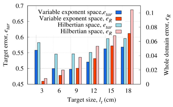
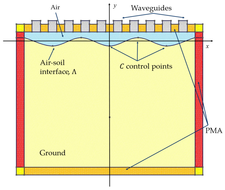
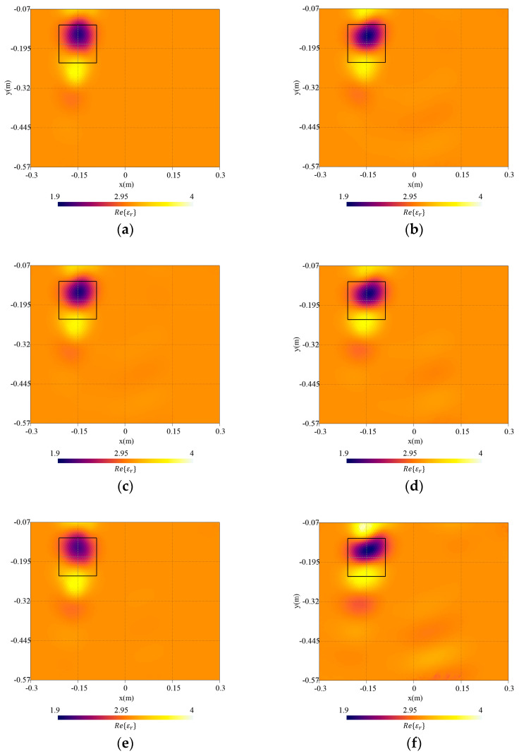
A microwave characterization technique to inspect subsurface scenarios is proposed and numerically assessed in this paper. The approach is based on a combination of finite element electromagnetic modeling and an inversion procedure in Lebesgue spaces with variable exponents. The former allows for description of the measurement system and subsurface scenario with high accuracy, while the latter exploits the adaptive definition of exponent function to achieve improved results in the regularized solution of the inverse scattering problem. The method has been assessed with numerical simulations regarding two-layered environments with both planar and non-planar air-soil interfaces. The results show the capabilities of the method of detecting buried objects in different operative conditions.

Keywords: Lebesgue spaces; finite element; inverse scattering; subsurface imaging.


Conflict of interest statement

The authors declare no conflict of interest.

Figures

Figure 1
Figure 1
Geometry of the shallow subsurface scenario.
Figure 2
Figure 2
Measurement system.
Figure 3
Figure 3
Sketch of simulation and investigation domains.
Figure 4
Figure 4
Flowchart of the inversion procedure.
Figure 5
Figure 5
Relative reconstruction errors in all of the investigation domain R and inside the target region versus the exponent range, defined by the parameter pmin.
Figure 6
Figure 6
Reconstructed distribution of the real part of the dielectric permittivity, Re{εr}, in the investigation domain R together with a square box indicating the shape of the actual target. Reference case.
Figure 7
Figure 7
Reconstructed distribution of the real part of the dielectric permittivity, Re{εr}, in the investigation domain R together with a square box indicating the shape of the actual target. Target with side length (a) lt=18 cm, (b) lt=12 cm, and (c) lt=3 cm.
Figure 8
Figure 8
Reconstruction errors in the whole investigation domain and inside the target region versus target size, lt with the variable exponent approach and classical Hilbertian space.
Figure 9
Figure 9
Reconstructed distribution of the real part of the reconstructed relative dielectric permittivity, Re{εr}, in the investigation domain R together with a square box indicating the shape of the actual target. Target centered at (a) yt=20 cm, (b) yt=25 cm, and (c) yt=32.5 cm.
Figure 10
Figure 10
Simulated and reconstructed scattering S-parameters (real and imaginary part) when the first antenna acts as the source. Target centered at (a) yt=20 cm and (b) yt=25 cm.
Figure 11
Figure 11
Reconstruction errors in the whole domain and inside the target versus the target size, yt.
Figure 12
Figure 12
Reconstructed distribution of the real part of the dielectric permittivity, Re{εr}, in the investigation domain R together with a square box indicating the shape of the actual target. The case of two buried targets with different geometry.
Figure 13
Figure 13
Reconstructed distribution of the real part of the dielectric permittivity, Re{εr}, in the investigation domain R together with a square box indicating the shape of the actual target. Background dielectric permittivity in the inversion procedure: (a) underestimation (εr,b*=εr,b0.5) and (b) overestimation (εr,b*=εr,b+0.5).
Figure 14
Figure 14
Measurement and subsurface model in the forward solver.
Figure 15
Figure 15
Reconstruction errors in the whole domain and inside the target versus the RMS height of the air–soil interface, hrms.
Figure 16
Figure 16
Reconstructed distribution of the real part of the complex dielectric permittivity, Re{εr}, in the investigation domain together with a square box indicating the shape of the actual target. Cases of surface with hrms=λ30 and inversion with (a) exact interfaces and (b) planar interfaces; hrms=λ20 and inversion with (c) exact interfaces and (d) planar interfaces; and hrms=λ10 inversion with (e) exact interfaces and (f) planar interfaces.

References

    1. Persico R. Introduction to Ground Penetrating Radar: Inverse Scattering and Data Processing. John Wiley & Sons; Hoboken, NJ, USA: 2014.
    1. Benedetto A., Pajewski L. Civil Engineering Applications of Ground Penetrating Radar. Springer; Cham, Switzerland: 2015.
    1. Frigui H., Zhang L., Gader P.D. Context-Dependent Multisensor Fusion and Its Application to Land Mine Detection. IEEE Trans. Geosci. Remote Sens. 2010;48:2528–2543. doi: 10.1109/TGRS.2009.2039936. - DOI
    1. Pastorino M., Randazzo A. Microwave Imaging Methods and Applications. Artech House; London, UK: 2018.
    1. Salucci M., Oliveri G., Massa A. GPR Prospecting through an Inverse-Scattering Frequency-Hopping Multifocusing Approach. IEEE Trans. Geosci. Remote Sens. 2015;53:6573–6592. doi: 10.1109/TGRS.2015.2444391. - DOI

LinkOut - more resources