

A Wearable-Sensor System with AI Technology for Real-Time Biomechanical Feedback Training in Hammer Throw
- PMID: 36617025
- PMCID: PMC9824395
- DOI: 10.3390/s23010425
A Wearable-Sensor System with AI Technology for Real-Time Biomechanical Feedback Training in Hammer Throw
Abstract
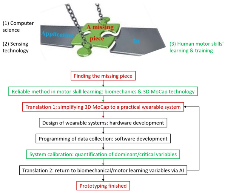
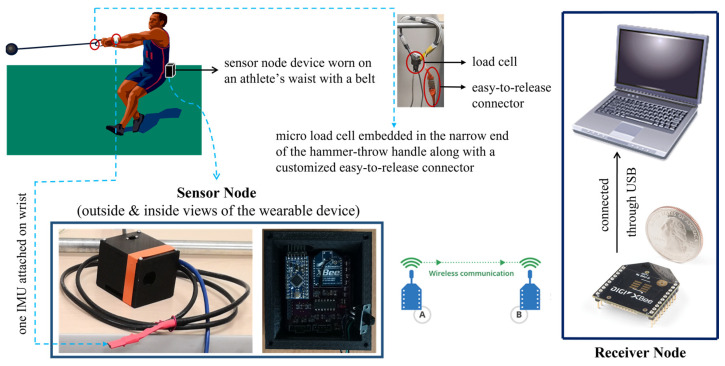
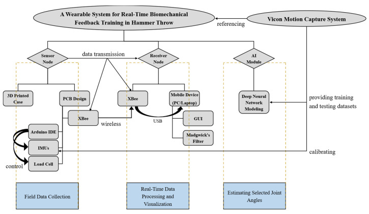
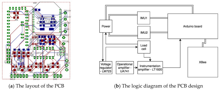
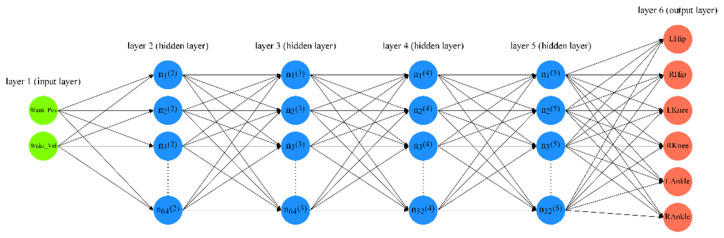
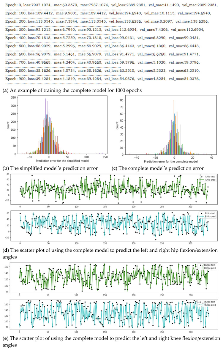
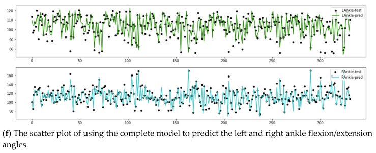
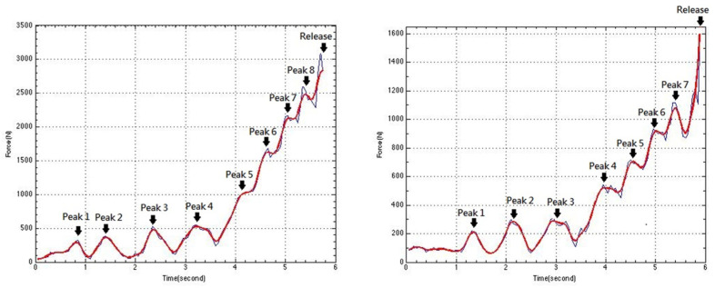
Developing real-time biomechanical feedback systems for in-field applications will transfer human motor skills' learning/training from subjective (experience-based) to objective (science-based). The translation will greatly improve the efficiency of human motor skills' learning and training. Such a translation is especially indispensable for the hammer-throw training which still relies on coaches' experience/observation and has not seen a new world record since 1986. Therefore, we developed a wearable wireless sensor system combining with artificial intelligence for real-time biomechanical feedback training in hammer throw. A framework was devised for developing such practical wearable systems. A printed circuit board was designed to miniaturize the size of the wearable device, where an Arduino microcontroller, an XBee wireless communication module, an embedded load cell and two micro inertial measurement units (IMUs) could be inserted/connected onto the board. The load cell was for measuring the wire tension, while the two IMUs were for determining the vertical displacements of the wrists and the hip. After calibration, the device returned a mean relative error of 0.87% for the load cell and the accuracy of 6% for the IMUs. Further, two deep neural network models were built to estimate selected joint angles of upper and lower limbs related to limb coordination based on the IMUs' measurements. The estimation errors for both models were within an acceptable range, i.e., approximately ±12° and ±4°, respectively, demonstrating strong correlation existed between the limb coordination and the IMUs' measurements. The results of the current study suggest a remarkable novelty: the difficulty-to-measure human motor skills, especially in those sports involving high speed and complex motor skills, can be tracked by wearable sensors with neglect movement constraints to the athletes. Therefore, the application of artificial intelligence in a wearable system has shown great potential of establishing real-time biomechanical feedback training in various sports. To our best knowledge, this is the first practical research of combing wearables and machine learning to provide biomechanical feedback in hammer throw. Hopefully, more wearable biomechanical feedback systems integrating artificial intelligence would be developed in the future.
Keywords: deep learning; hammer throw; real-time biomechanical feedback; wearable devices; wireless sensor systems.
Conflict of interest statement
The authors declare no conflict of interest.
Figures

Similar articles
-
A wireless sensor system for a biofeedback training of hammer throwers.Springerplus. 2016 Aug 22;5(1):1395. doi: 10.1186/s40064-016-3069-5. eCollection 2016. Springerplus. 2016. PMID: 27610314 Free PMC article.
-
A machine learning approach to real-time calculation of joint angles during walking and running using self-placed inertial measurement units.Gait Posture. 2025 May;118:85-91. doi: 10.1016/j.gaitpost.2025.01.028. Epub 2025 Jan 26. Gait Posture. 2025. PMID: 39914248
-
A Wide-Range, Wireless Wearable Inertial Motion Sensing System for Capturing Fast Athletic Biomechanics in Overhead Pitching.Sensors (Basel). 2019 Aug 21;19(17):3637. doi: 10.3390/s19173637. Sensors (Basel). 2019. PMID: 31438549 Free PMC article.
-
Using Wearable Sensors to Estimate Mechanical Power Output in Cyclical Sports Other than Cycling-A Review.Sensors (Basel). 2022 Dec 21;23(1):50. doi: 10.3390/s23010050. Sensors (Basel). 2022. PMID: 36616649 Free PMC article. Review.
-
Motion Capture Technology in Sports Scenarios: A Survey.Sensors (Basel). 2024 May 6;24(9):2947. doi: 10.3390/s24092947. Sensors (Basel). 2024. PMID: 38733052 Free PMC article. Review.
Cited by
-
Special Issue "Biomechanical Analysis in Physical Activity and Sports".J Funct Morphol Kinesiol. 2025 Mar 30;10(2):116. doi: 10.3390/jfmk10020116. J Funct Morphol Kinesiol. 2025. PMID: 40566413 Free PMC article.
-
Microsystem Advances through Integration with Artificial Intelligence.Micromachines (Basel). 2023 Apr 8;14(4):826. doi: 10.3390/mi14040826. Micromachines (Basel). 2023. PMID: 37421059 Free PMC article. Review.
-
Artificial intelligence and glaucoma: a lucid and comprehensive review.Front Med (Lausanne). 2024 Dec 16;11:1423813. doi: 10.3389/fmed.2024.1423813. eCollection 2024. Front Med (Lausanne). 2024. PMID: 39736974 Free PMC article. Review.
References
-
- Shan G., Visentin P., Zhang X., Hao W., Yu D. Bicycle kick in soccer: Is the virtuosity systematically entrainable? Sci. Bull. 2015;60:819–821. doi: 10.1007/s11434-015-0777-0. - DOI
MeSH terms
Grants and funding
- 2020YFC2005803/National Key Research and Development Project from Ministry of Science and Technology of the People's Republic of China
- 62003331/National Natural Science Foundation of China
- GJHZ2021132/China-Japan International Collaboration Project from Chinese Academy of Sciences
- RGPIN-2014-03648/Natural Sciences and Engineering Research Council
LinkOut - more resources
Full Text Sources
