

High-performance Fe(Se,Te) films on chemical CeO2-based buffer layers
- PMID: 36631475
- PMCID: PMC9834258
- DOI: 10.1038/s41598-022-24044-5
High-performance Fe(Se,Te) films on chemical CeO2-based buffer layers
Abstract
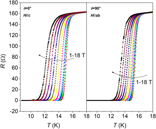
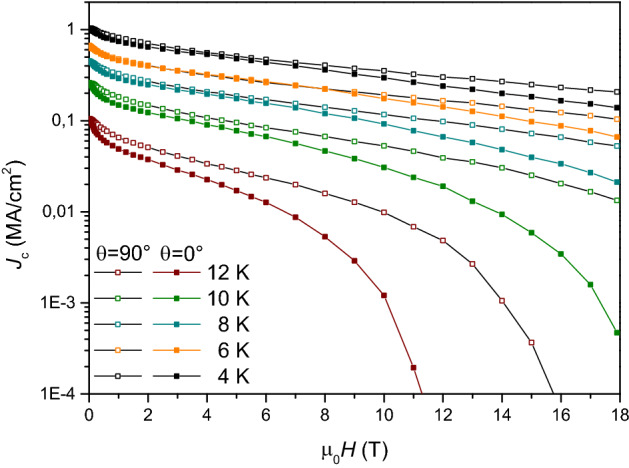
The fabrication of a Fe-based coated conductor (CC) becomes possible when Fe(Se,Te) is grown as an epitaxial film on a metallic oriented substrate. Thanks to the material's low structural anisotropy, less strict requirements on the template microstructure allow for the design of a simplified CC architecture with respect to the REBCO multi-layered layout. This design, though, still requires a buffer layer to promote the oriented growth of the superconducting film and avoid diffusion from the metallic template. In this work, Fe(Se,Te) films are grown on chemically-deposited, CeO2-based buffer layers via pulsed laser deposition, and excellent properties are obtained when a Fe(Se,Te) seed layer is used. Among all the employed characterization techniques, transmission electron microscopy proved essential to determine the actual effect of the seed layer on the final film properties. Also, systematic investigation of the full current transport properties J(θ, H, T) is carried out: Fe(Se,Te) samples are obtained with sharp superconducting transitions around 16 K and critical current densities exceeding 1 MA cm-2 at 4.2 K in self-field. The in-field and angular behavior of the sample are in line with data from the literature. These results are the demonstration of the feasibility of a Fe-based CC, with all the relative advantages concerning process simplification and cost reduction.
© 2023. The Author(s).
Conflict of interest statement
The authors declare no competing interests.
Figures


References
-
- Palenzona A, et al. A new approach for improving global critical current density in Fe(Se0.5Te0.5) polycrystalline materials. Supercond. Sci. Technol. 2012;25:115018. doi: 10.1088/0953-2048/25/11/115018. - DOI
-
- Bruzzone P, et al. High temperature superconductors for fusion magnets. Nucl. Fusion. 2018;58:1030001. doi: 10.1088/1741-4326/aad835. - DOI
-
- Hosono H, Yamamoto A, Hiramatsu H, Ma Y. Recent advances in iron-based superconductors toward applications. Mater. Today. 2018;21:278–302. doi: 10.1016/j.mattod.2017.09.006. - DOI
-
- Pallecchi I, Eisterer M, Malagoli A, Putti M. Application potential of Fe-based superconductors. Supercond. Sci. Technol. 2015;28:114005. doi: 10.1088/0953-2048/28/11/114005. - DOI
Grants and funding
LinkOut - more resources
Full Text Sources
