. 2023 Jan;613(7943):280-286.
doi: 10.1038/s41586-022-05421-6. Epub 2023 Jan 11.

An electric molecular motor

Affiliations

An electric molecular motor

Long Zhang et al. Nature. 2023 Jan.

Abstract

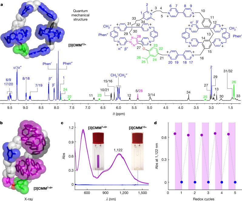
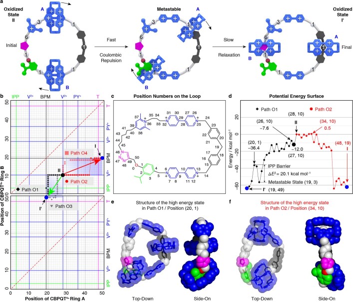
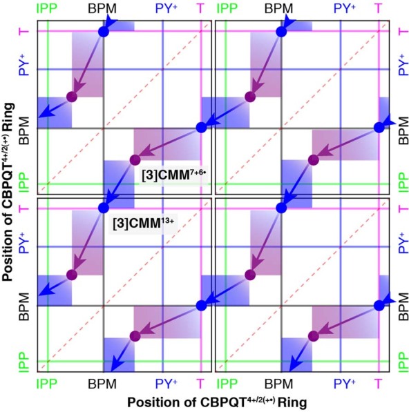
Macroscopic electric motors continue to have a large impact on almost every aspect of modern society. Consequently, the effort towards developing molecular motors1-3 that can be driven by electricity could not be more timely. Here we describe an electric molecular motor based on a [3]catenane4,5, in which two cyclobis(paraquat-p-phenylene)6 (CBPQT4+) rings are powered by electricity in solution to circumrotate unidirectionally around a 50-membered loop. The constitution of the loop ensures that both rings undergo highly (85%) unidirectional movement under the guidance of a flashing energy ratchet7,8, whereas the interactions between the two rings give rise to a two-dimensional potential energy surface (PES) similar to that shown by FOF1 ATP synthase9. The unidirectionality is powered by an oscillating10 voltage11,12 or external modulation of the redox potential13. Initially, we focused our attention on the homologous [2]catenane, only to find that the kinetic asymmetry was insufficient to support unidirectional movement of the sole ring. Accordingly, we incorporated a second CBPQT4+ ring to provide further symmetry breaking by interactions between the two mobile rings. This demonstration of electrically driven continual circumrotatory motion of two rings around a loop in a [3]catenane is free from the production of waste products and represents an important step towards surface-bound14 electric molecular motors.


Conflict of interest statement

The authors declare no competing interests.

Figures

Fig. 1
Fig. 1. Design and working mechanism of the [3]catenane molecular motor [3]CMM.
a, Graphical representations with key structural fragments for the oxidized state of the [3]catenane molecular motor [3]CMM13+. The cyclobis(paraquat-p-phenylene) rings, the bisradical dicationic states of cyclobis(paraquat-p-phenylene), the viologens, the radical cationic states of the viologens, the bis(4-methylenephenyl)methane, the isopropylphenylene, the triazole and the 2,6-dimethypyridinium units are labelled as CBPQT4+, CBPQT2(+•), V2+, V+•, BPM, IPP, T and PY+, respectively. b, Graphical representations for the reduced state of the [3]catenane molecular motor [3]CMM7+6• with key superstructural formulas showing the radical-pairing interactions between the CBPQT2(+•) rings and the V+• units. Positive charges are balanced by PF6 counterions, which are omitted for the sake of clarity. c, The redox operation of [3]CMM13+/7+6 demonstrating the unidirectional rotary motion of the two CBPQT4+/CBPQT2+• rings. In state I, [CBPQT-A]4+ and [CBPQT-B]4+ are positioned around the T and BPM units, respectively. Reduction of the V2+ units and the CBPQT4+ rings by the injection (step 1) of six electrons in total triggers both rings to undergo a clockwise rotation, leading to the formation (state II) of the reduced state [3]CMM7+6•. Subsequent oxidation by the removal (step 2) of six electrons restores the Coulombic repulsion between the two rings and the loop, obliging [CBPQT-B]4+ to thread over (state III) the steric barrier (IPP) under thermal activation and eventually encircle T, whereas [CBPQT-A]4+ finds itself threaded around BPM, thus completing a 180° positional exchange between the two rings shown in state I′. A second redox cycle (steps 3 and 4) resets the system back to state I after the accomplishment of another 180° positional exchange between the two rings.
Fig. 2
Fig. 2. Characterization of the redox state and electrically driven operation of the [3]catenane molecular motor [3]CMM.
a, Structural formula for the oxidized state [3]CMM13+ with an optimized quantum mechanical model structure (M06-2X/6-31G* basis set, in tubular with superimposed space-filling representation) and the 1H NMR spectrum (500 MHz, CD3COCD3, 298 K), in which all the proton assignments are labelled. b, X-ray single-crystal structure of the reduced state [3]CMM7+6• depicted by tubular with superimposed space-filling representations. Solvent molecules, counterions and hydrogen atoms are omitted for the sake of clarity. c, Vis/NIR spectra of the reduced state [3]CMM7+6• (purple) and the oxidized state [3]CMM13+ (blue) during the electrically driven operation of the molecular motor. Conditions: [3]CMM (30 μM), MeCN solution with TBAPF6 (0.1 M) as the supporting electrolyte, reduction potential −0.5 V (versus Ag/AgCl) for 10 min, oxidation potential +0.7 V (versus Ag/AgCl) for 15 min. Insets are photographs of the two solutions in the oxidized (colourless) and reduced (purple) states. d, Absorption intensities of [3]CMM7+6• (purple) and [3]CMM13+ (blue) at 1,122 nm, showing the reversible switching between the two redox states during each cycle. Abs, absorption; ppm, parts per million.
Fig. 3
Fig. 3. Measurement of the unidirectionality.
Top: graphical representation of the positional exchange of the deuterium-labelled CBPQT4+ and CBPQT4+ rings on the loop after one redox cycle. Bottom: partial 1H NMR (600 MHz, CD3COCD3, 298 K) spectra of [Dn]-[3]CMM•13PF6 with proton assignments before (left) and after (right) one electrically driven redox cycle. Numbers under peaks indicate relative integrals. ppm, parts per million.
Fig. 4
Fig. 4. Metastable state in the redox cycle.
a, Top, graphical representation and structural formula of the metastable state with an optimized quantum mechanical model structure (M06-2X/6-31G* basis set, in tubular with superimposed space-filling representation). Bottom, partial 1H NMR (600 MHz, CD3CN, 298 K) spectra of [3]CMM•13PF6 measured over time (0–60 min) immediately after a cycle of reduction (Cp2Co) and reoxidation (NOPF6), with proton assignments labelled at the top and bottom of the spectra. The proton resonances attributable to the metastable state are labelled with an asterisk. b, Top, thermal relaxation associated with the co-conformational rearrangement from the metastable state to the reoxidized state. The activation energy barrier ΔG of 21.6 kcal mol−1 was determined using the Eyring equation (k=kBTheΔGRT), in which k is the reaction rate constant, T is the absolute temperature, R is the gas constant, kB is the Boltzmann constant and h is the Planck constant. Bottom, plot of the changes in the normalized integral of protons on the BPM (H-12* and H-14) and IPP (H-22* and H-25) units with time at 298 K during the transformation from the metastable to the reoxidized state, as well as the fitting curves of these data according to the first-order kinetic model. ppm, parts per million.
Extended Data Fig. 1
Extended Data Fig. 1. Calculated PES of the oxidized [2]catenane [2]C9+.
a, The potential energy for the CBPQT4+ ring traversing the loop in the oxidized state. The numbered atoms on the loop are used to define the position of the CBPQT4+ ring. b, Graphical representation of the oxidized state of the [2]catenane [2]C9+. c, Graphical representation of the calculated PES of the CBPQT4+ ring moving around the loop, shown in a rollercoaster manner for the fully oxidized [2]C9+.
Extended Data Fig. 2
Extended Data Fig. 2. Calculated PES of the reduced [2]catenane [2]C5+4•.
a, The potential energy for the CBPQT2(+•) ring as a function of its position on the loop in the reduced state of the [2]catenane [2]C5+4•. The numbered atoms on the loop are used to define the position of the CBPQT2(+•) ring. b, Graphical representation of the reduced state of [2]catenane [2]C5+4• in its lowest-energy co-conformation in which the CBPQT2(+•) ring encircles the V+• unit, position 10. c, Graphical representation of calculated potential energy of the CBPQT2(+•) ring as it moves around the loop, shown in a rollercoaster manner for the radical state [2]C5+4•. d, Quantum mechanical minimized structures (M06-2X/6-31G* basis set) for the CBPQT2(+•) ring located at positions 10, 21 and 27, respectively.
Extended Data Fig. 3
Extended Data Fig. 3. Calculated PES of the reduced [3]catenane [3]CMM7+6•.
a, Graphical representations of the redox process experienced by the [3]catenane in going from the oxidized state I (48, 19) to the reduced state II (28, 10). b, A two-dimensional position map describing the movement of the two reduced CBPQT2(+•) rings (A and B) around the loop. Four hypothetical paths (R1–R4) during the reduction process are illustrated by diamond (grey), circle (light red), triangle (black) and square (red) symbols, respectively. The green arrow indicates the preferred direction of movement and the red arrow indicates the less preferred (nearly precluded) direction of movement. The green, purple, black, blue and magenta lines represent the positions of the IPP, V+•, BPM, PY+ and T units, respectively. The dashed red diagonal lines represent barriers that cannot be crossed physically because doing so would require the two CBPQT2(+•) rings to occupy the same space. c, The PESs of the two CBPQT2(+•) rings moving around the loop in the reduced state, starting from point I (48, 19) and following paths R3 and R4, respectively. d, Structural formula of the loop with atoms numbered to define the positions of the CBPQT2(+•) rings. e,f, Quantum mechanical minimized structures (M06-2X/6-31G* basis set, top-down and side-on views) for the CBPQT2(+•) rings at positions (32, 10) and (2, 28), respectively.
Extended Data Fig. 4
Extended Data Fig. 4. Calculated PES of the oxidized [3]catenane [3]CMM13+.
a, Graphical representations of the process experienced by the [3]catenane in going from the oxidized state II (28, 10) to the oxidized state I′ (19, 49). b, A two-dimensional position map describing the movement of the two oxidized CBPQT4+ rings (A and B) around the loop. Four hypothetical paths O1–O4 during the oxidation process are illustrated by diamond (black), circle (red), triangle (grey) and square (light red) symbols, respectively. The green arrow indicates the preferred direction of movement and the red arrow indicates the less preferred (nearly precluded) direction of movement. The green, blue, black, blue and magenta lines represent the positions of the IPP, V2+, BPM, PY+ and T units, respectively. The dashed red diagonal line represents a barrier that cannot be crossed physically because the two CBPQT4+ rings would occupy the same space. c, Structural formula of the loop with atoms numbered to define the positions of the CBPQT4+ rings. d, The PESs of the two CBPQT4+ rings moving around the loop in the oxidized state starting from point II (28, 10) and following paths O1 and O2, respectively. The value for the energy barrier ΔE of 20.1 kcal mol−1 was determined from the energy difference between the positions (19, 3) and (20, 1). The position (19, 3) corresponds to the metastable state on path O1. e,f, Quantum mechanical minimized structures (M06-2X/6-31G* basis set, top-down and side-on views) for the CBPQT4+ rings at positions (20, 1) and (34, 10), respectively. Quantum mechanical minimized structures of the lowest-energy state (19, 48) and metastable state (21, 3) are presented in Figs. 2a and 4a, respectively.
Extended Data Fig. 5
Extended Data Fig. 5. A two-dimensional position map describing the movement of two CBPQT4+/2(+•) rings around the loop.
The x and y axes represent the positions of the CBPQT4+/2(+•) rings on the loop. The green, black, blue and magenta lines represent the positions of the IPP, BPM, PY+ and T units, respectively. The hypothetical paths involving switching of the [3]catenane [3]CMM during the redox cycles are illustrated in blue (oxidation) with purple (reduction) arrows, which are periodic on account of the cyclic nature of the loop. The trajectories indicate that, for unidirectional motion, there is a Coulombic barrier (PY+) and a steric barrier (IPP) under reducing and oxidizing conditions, respectively. The dashed red diagonal line represents a barrier that cannot be crossed physically for the simple reason that two CBPQT4+/2(+•) rings would end up occupying the same space.
Extended Data Fig. 6
Extended Data Fig. 6. Scan-rate variation (0.02–2.0 V s−1) of cyclic voltammograms of [3]CMM•13PF6 (0.5 mM).
As the scan rate is increased to 2.0 V s−1, only one reduction peak for the radical state [3]CMM7+6• is observed, indicating that the electron-transfer process is much faster than ring movement at this fast scan rate. This observation suggests that, under the experimental conditions used during the operation of the [3]catenane motor, the reduction to the radical state [3]CMM7+6• and the reoxidation to the fully oxidized state [3]CMM13+ is completed fully and very rapidly.
Extended Data Fig. 7
Extended Data Fig. 7. Electrically driven operation of [3]CMM.
a, Graphical illustration of the electrochemical cell used in the repeated controlled potential electrolysis experiments. CE, counter electrode; RE, reference electrode; WE, working electrode. b, Photographs of the oxidized state (left) [3]CMM13+ and the reduced state (right) [3]CMM7+6• in the electrochemical cell.
Extended Data Fig. 8
Extended Data Fig. 8. Synthesis of the deuterium-labelled [3]catenane [Dn]-[3]CMM.
By sequentially adding [D16]-CBPQT2(+•) and CBPQT2(+•) during the synthesis of [Dn]-[3]CMM, it is able to bias the distribution of the undeuterated CBPQT4+ rings on the T and BPM units. The [3]catenane [Dn]-[3]CMM13+ was obtained as a mixture of four isotopologues, including [D0]-[3]CMM13+, and [D32]-[3]CMM13+, in addition to two co-constitutional isomers [D16]-[3]CMM13+. CuAAC, copper(I)-catalysed azide–alkyne cycloaddition.
Extended Data Fig. 9
Extended Data Fig. 9. Calculation of the probability of 180° rotation for both rings on the loop.
Distribution of CBPQT4+ rings on the two positions (T and BPM) of the cyclic track according to the 1H NMR spectra (Fig. 3) of [Dn]-[3]CMM•13PF6 before and after one redox cycle, based on the relevant integration of protons H-Phen″ (I1/I1′) and H-Phen′ (I2/I2′), respectively. η, the probability of 180° rotation for both rings on the loop.
Extended Data Fig. 10
Extended Data Fig. 10. Probable direction of the movement of two CBPQT4+/2(+•) rings during the redox operation of [3]CMM13+.
Clockwise means that each CBPQT4+/2(+•) ring sees the substituents on the loop in the order T → PY+ → V2+/+• → V2+/+• → IPP → T and counterclockwise means that each ring sees the substituents on the loop in the order T → IPP → V2+/+• → V2+/+• → PY+ → T. The curly arrows represent the direction in which the two rings move around the loop. The ‘pred’ and ‘pox’ near the arrows are the probability of clockwise motion of the two rings on the loop in the redox cycle. The kred,+, kred,−, kox,− and kox,+ are the corresponding rate constants for the probable steps during the redox cycle, respectively, and the clockwise and counterclockwise steps are also indicated by ‘+’ and ‘−’, respectively. The 180° rotation is represented by ‘1/2’.

References

    1. Astumian RD. Making molecules into motors. Sci. Am. 2001;285:56–64. doi: 10.1038/scientificamerican0701-56. - DOI - PubMed
    1. Kassem S, et al. Artificial molecular motors. Chem. Soc. Rev. 2017;46:2592–2621. doi: 10.1039/C7CS00245A. - DOI - PubMed
    1. Baroncini M, Silvi S, Credi A. Photo- and redox-driven artificial molecular motors. Chem. Rev. 2020;120:200–268. doi: 10.1021/acs.chemrev.9b00291. - DOI - PubMed
    1. Leigh DA, Wong JKY, Dehez F, Zerbetto F. Unidirectional rotation in a mechanically interlocked molecular rotor. Nature. 2003;424:174–179. doi: 10.1038/nature01758. - DOI - PubMed
    1. Erbas-Cakmak S, et al. Rotary and linear molecular motors driven by pulses of a chemical fuel. Science. 2017;358:340–343. doi: 10.1126/science.aao1377. - DOI - PubMed

Publication types