Review
. 2023 Mar;10(8):e2206478.
doi: 10.1002/advs.202206478. Epub 2023 Jan 18.

Protonic Ceramic Electrochemical Cells for Synthesizing Sustainable Chemicals and Fuels

Affiliations
Review

Protonic Ceramic Electrochemical Cells for Synthesizing Sustainable Chemicals and Fuels

Fan Liu et al. Adv Sci (Weinh). 2023 Mar.

Abstract

Protonic ceramic electrochemical cells (PCECs) have been intensively studied as the technology that can be employed for power generation, energy storage, and sustainable chemical synthesis. Recently, there have been substantial advances in electrolyte and electrode materials for improving the performance of protonic ceramic fuel cells and protonic ceramic electrolyzers. However, the electrocatalytic materials development for synthesizing chemicals in PCECs has gained less attention, and there is a lack of systematic and fundamental understanding of the PCEC reactor design, reaction mechanisms, and electrode materials. This review comprehensively summarizes and critically evaluates the most up-to-date progress in employing PCECs to synthesize a wide range of chemicals, including ammonia, carbon monoxide, methane, light olefins, and aromatics. Factors that impact the conversion, selectivity, product yield, and energy efficiencies are discussed to provide new insights into designing electrochemical cells, developing electrode materials, and achieving economically viable chemical synthesis. The primary challenges associated with producing chemicals in PCECs are highlighted. Approaches to tackle these challenges are then offered, with a particular focus on deliberately designing electrode materials, aiming to achieve practically valuable product yield and energy efficiency. Finally, perspectives on the future development of PCECs for synthesizing sustainable chemicals are provided.

Keywords: CO2 reduction; ammonia synthesis; natural gas upgrading; protonic ceramic electrochemical fuel cells; sustainable chemical synthesis.


Conflict of interest statement

The authors declare no conflict of interest.

Figures

Figure 1
Figure 1
Applications of PCECs for sustainable chemical synthesis.
Figure 2
Figure 2
Schematic illustration of four primary PCEC configurations developed for ammonia synthesis. A) Reactor 1 that converts H2 and N2 to ammonia in a two‐chamber configuration, B) single‐chamber Reactor 2 that electrochemically promotes ammonia synthesis, C) Reactor 3 that intensifies steam methane reforming with ammonia synthesis, and D) Reactor 4 that converts H2O and N2 to ammonia. OER: oxygen evolution reaction. HOR: hydrogen oxidation reaction. HER: hydrogen evolution reaction. NRR: nitrogen reduction reaction. SMR: steam methane reforming. WGSR: water gas shift reaction.
Figure 3
Figure 3
Thermodynamics and corresponding reversible electrochemical potential of three ammonia synthesis reactions calculated under the standard pressure.
Figure 4
Figure 4
Electrical energy consumption of synthesizing ammonia in PCECs.[ 14 , 48 , 50 , 51 , 52 , 55 , 56 , 59 ] The electrical energy consumption is determined based on the experimental results reported in papers published in the last two decades. Cross and star symbols represent the PCECs with Reaction 1 configuration. Open symbols represent single‐chamber PCECs with Reactor 2 configuration. Solid symbols denote PCECs with Reactor 3 configuration. Half‐solid and half‐open symbols stand for PCECs with Reactor 4 configuration. Next‐generation Reactor 4 indicates the targets of synthesizing ammonia in PCECs. The green dash line represents the total energy consumption for the Haber–Bosch process.
Figure 5
Figure 5
Potential NRR pathways in PCECs. A) Dissociative electrochemical mechanism (Pathway 1). B) Associate thermochemical mechanism (Pathway 2).
Figure 6
Figure 6
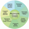
Summary of the strategies proposed for enhancing ammonia production in PCECs.
Figure 7
Figure 7
The ammonia production rate and Faradaic Selectivity toward ammonia as a function of the current density of PCECs.
Figure 8
Figure 8
Schematic illustration of PCECs for carbon‐containing chemical synthesis via CO2 reduction reaction.
Figure 9
Figure 9
Thermodynamics of CO2 reduction in PCECs under standard atmosphere. A) The Gibbs free energy change of half‐cell reaction and corresponding CO2 reduction potentials versus the potential of HER (i.e., 2H+ + 2e = H2(g)). The product of CO2 reduction is CH4. B) The Gibbs free energy change of half‐cell reaction and corresponding CO2 reduction potentials versus the potential of HER. The product of CO2 reduction is CO. The assumption in Figure 9A,B is that the potential of HER is zero and it does not change with operating temperatures. The equilibrium potential of CO2 reduction is calculated based on E = − ΔG/nF. C) The thermodynamics of CO2 reduction with various feedstocks and CO as the final product. D) The thermodynamics of CO2 reduction with various feedstocks and CH4 as the final product.
Figure 10
Figure 10
CO2 reduction in CO2‐PCEC 2 with BaCe0.7Zr0.1Y0.1Yb0.1O3+Ni (BCZYYb7111+Ni) as the negative electrode. A) Production rate of chemicals produced in a button cell.[ 5 ] Copyright 2019, The Authors, published by Springer Nature. B) CO2 conversion in a button cell. Reproduced under the terms of the Creative Commons Attribution 4.0 International License.[ 5 ] Copyright 2019, The Authors, published by Springer Nature. C) CH4 selectivity in a button cell.[ 5 ] Copyright 2019, The Authors, published by Springer Nature. D) CH4 selectivity in a large area cell (5 cm2). Reproduced with permission.[ 98 ] Copyright 2022, Elsevier.
Figure 11
Figure 11
CO2 reduction in CO2‐PCEC 1 with three different negative electrodes. Reproduced with permission.[ 28 ] Copyright 2021, Springer Nature. A) I‐V curve of CO2 reduction. B) CO Faradaic selectivity and CO production rate. C) CH4 Faradaic selectivity and CH4 production rate.
Figure 12
Figure 12
The selectivity of CO2 reduction toward CH4 and CO in PCECs has been recently demonstrated.[ 5 , 28 , 86 , 87 , 90 ] A) The selectivity of CO as a function of operating temperature. B) The selectivity of CH4 as a function of operating temperature. C) The Faradaic selectivity of H2 as a function of operating temperature.
Figure 13
Figure 13
Schematic illustration of the proposed CO2RR mechanisms in PCECs. The blue rectangle is the proton‐conducting electrolyte membrane. The brown dots are the oxide supports and the green dots are metallic particles, which act as the CO2 electrode.
Figure 14
Figure 14
Summary of challenges and future perspectives to improve the chemical synthesis in PCECs via CO2RR.
Figure 15
Figure 15
Pathways of synthesizing chemicals from natural gas/methane. NG: natural gas; FTS: Fischer–Tropsch synthesis; MTO: methanol to olefins; MTA: methanol to aromatics; OCM: oxidative coupling of methane; AMO: Aromatization of methane under oxidizing atmosphere; MDA: methane dehydroaromatization.
Figure 16
Figure 16
Schematic illustration of PCECs for producing aromatics from natural gas. A) PCECs with a mixed proton and oxygen‐ion conductor as the membrane. B) PCECs with a mixed proton, oxygen‐ion, and electronic conductor as the membrane. MA: methane aromatization; MIEC: mixed ionic and electronic conductor; MDA: methane dehydroaromatization.
Figure 17
Figure 17
Impacts of H2 extraction and O2 injection on methane aromatization.
Figure 18
Figure 18
Converting CH4 to aromatics in PCECs. Reproduced with permission.[ 23 ] Copyright 2016, AAAS. A) A Tubular reactor with the proton‐conducting membrane. B) The aromatic yield and CO yield as a function of H2 extracted and O2 injected. C) Deactivation rate constant as a function of H2 extracted and O2 injected.
Figure 19
Figure 19
Converting C2H6 to light olefins in PCECs. Reproduced with permission.[ 157 ] Copyright 2021, American Chemistry Society. A) Planar reactor with a proton‐conducting membrane for converting C2H6 to light olefins. B) Conversion of C2H6 and C2H4 yield as a function of applied current density. C) Product selectivity as a function of applied current density.
Figure 20
Figure 20
Direct nonoxidative methane conversion (DNMC) transforms CH4 to higher (C2+) hydrocarbons and H2 in an MIEC membrane. Reproduced with permission.[ 158 ] Copyright 2021, Wiley‐VCH. A) Tubular reactor with a MIEC as the membrane. B) CH4 conversion and product yield achieved in a fixed‐bed reactor and the tubular membrane reactor using different gas to seep the H2. C) Product selectivity achieved in a fixed‐bed reactor and the tubular membrane reactor using different gas to seep the H2.

References

    1. Duan C., Kee R. J., Zhu H., Karakaya C., Chen Y., Ricote S., Jarry A., Crumlin E. J., Hook D., Braun R., Sullivan N. P., O'Hayre R., Nature 2018, 557, 217. - PubMed
    1. Duan C., Tong J., Shang M., Nikodemski S., Sanders M., Ricote S., Almansoori A., O'Hayre R., Science 2015, 349, 1321. - PubMed
    1. Bian W., Wu W., Wang B., Tang W., Zhou M., Jin C., Ding H., Fan W., Dong Y., Li J., Nature 2022, 604, 479. - PubMed
    1. Ding H., Wu W., Jiang C., Ding Y., Bian W., Hu B., Singh P., Orme C. J., Wang L., Zhang Y., Ding D., Nat. Commun. 2020, 11, 1907. - PMC - PubMed
    1. Duan C., Kee R., Zhu H., Sullivan N., Zhu L., Bian L., Jennings D., O'Hayre R., Nat. Energy 2019, 4, 230.

LinkOut - more resources