

Investigation of Interlayer Interface Strength and Print Morphology Effects in Fused Deposition Modeling 3D-Printed PLA
- PMID: 36655175
- PMCID: PMC9828590
- DOI: 10.1089/3dp.2020.0109
Investigation of Interlayer Interface Strength and Print Morphology Effects in Fused Deposition Modeling 3D-Printed PLA
Abstract
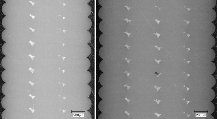
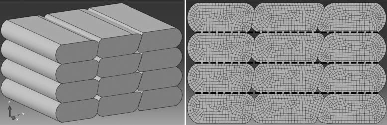
Fused deposition modeling polymer 3D printing has become a popular versatile additive manufacturing technology. However, there are limitations to the mechanical properties due to the layer-by-layer deposition approach. The relatively low strength of the interface between layers is the cause for potential microstructural weak points in such printed components. The interface strength of 3D-printed Polylactic Acid (PLA) polymer was determined through physical tensile testing in combination with microstructural finite element method (FEM) simulations. A custom tensile specimen was created to isolate the interlayer interfaces for direct testing of interface strength. Tensile tests resulted in an average 2.4 GPa stiffness and an average 22.8 MPa tensile strength for printed specimens, corresponding to a 32.4% and 47.8% reduction from the bulk filament stiffness and strength, respectively. Sectioned tensile specimens were observed under a digital microscope to examine microstructural features such as inter-layer gaps, extrusion cross-section, and voids. These were measured to create accurate FEM microstructural model geometries. The brittle fracture that occurred during the tensile testing was due to debonding of the interfaces. This was represented in Abaqus by using cohesive surfaces. Interface strength was inferred by varying the strength of the cohesive surfaces until the simulation mechanical response matched the physical tests. The resulting interface strength of the PLA polymer was 33.75 MPa on average, corresponding to a 22.5% reduction from bulk properties. Potential improvements to the overall strength of the 3D printed PLA were investigated in simulation by parameterizing improved gap morphologies. As the size of the interlayer gaps decreased, the stiffness and strength of the printed parts improved, whereas completely eliminating gaps resulted in a potential 16.1% improvement in material stiffness and 19.8% improvement in strength. These models show that significant improvements can be made to the overall printed part performance by optimizing the printing process and eliminating inner voids.
Keywords: 3D printing; FDM interface strength; additive manufacturing; finite element modeling.
Copyright 2021, Mary Ann Liebert, Inc., publishers.
Conflict of interest statement
No competing financial interests exist.
Figures


Similar articles
-
Analysis of the Impact of Cooling Lubricants on the Tensile Properties of FDM 3D Printed PLA and PLA+CF Materials.Polymers (Basel). 2024 Aug 5;16(15):2228. doi: 10.3390/polym16152228. Polymers (Basel). 2024. PMID: 39125254 Free PMC article.
-
Morphology and Mechanical Properties of 3D Printed Wood Fiber/Polylactic Acid Composite Parts Using Fused Deposition Modeling (FDM): The Effects of Printing Speed.Polymers (Basel). 2020 Jun 11;12(6):1334. doi: 10.3390/polym12061334. Polymers (Basel). 2020. PMID: 32545359 Free PMC article.
-
Layer combination of similar infill patterns on the tensile and compression behavior of 3D printed PLA.Sci Rep. 2025 Apr 6;15(1):11759. doi: 10.1038/s41598-025-94446-8. Sci Rep. 2025. PMID: 40189629 Free PMC article.
-
Micromechanical Models for FDM 3D-Printed Polymers: A Review.Polymers (Basel). 2023 Nov 23;15(23):4497. doi: 10.3390/polym15234497. Polymers (Basel). 2023. PMID: 38231913 Free PMC article. Review.
-
3D Printing of Fiber-Reinforced Plastic Composites Using Fused Deposition Modeling: A Status Review.Materials (Basel). 2021 Aug 12;14(16):4520. doi: 10.3390/ma14164520. Materials (Basel). 2021. PMID: 34443044 Free PMC article. Review.
Cited by
-
Effects of high gravity on properties of parts fabricated using material extrusion system by additive manufacturing.Heliyon. 2024 May 31;10(11):e32161. doi: 10.1016/j.heliyon.2024.e32161. eCollection 2024 Jun 15. Heliyon. 2024. PMID: 38947488 Free PMC article.
-
Numerical Homogenization Calculation of Effective Stiffness of Fused Deposition Modeling Printing Carbon Fiber Reinforced Polylactic Acid Composites.3D Print Addit Manuf. 2024 Oct 22;11(5):e1863-e1876. doi: 10.1089/3dp.2023.0131. eCollection 2024 Oct. 3D Print Addit Manuf. 2024. PMID: 39741548
References
-
- Prater TJ, Bean RD, Ledbetter FE. Summary Report on Phase I Results From the 3D Printing in Zero-G Technology Demonstration Mission, Volume I. NASA/TP-2016-219101. Huntsville, AL: Marshall Space Flight Center.
-
- Gardner JM, Stelter CJ, Yashin EA, et al. . High Temperature Thermoplastic Additive Manufacturing Using Low-Cost, Open-Source Hardware. NASA/TM-2016-219344. Hampton, VA: NASA Langley Research Center.
-
- Wong JY, Pfahnl AC. 3D printing of surgical instruments for long-duration space missions. Aviat Space Environ Med 2014;85:758–763. - PubMed
-
- Subburaj K, Nair C, Rajesh S, et al. . Rapid development of auricular prosthesis using CAD and rapid prototyping technologies. Int J Oral Maxillofac Surg 2007;36:938–943. - PubMed
LinkOut - more resources
Full Text Sources
Research Materials
Miscellaneous