Review
. 2022 Dec 30;14(1):112.
doi: 10.3390/mi14010112.

Advances in BBB on Chip and Application for Studying Reversible Opening of Blood-Brain Barrier by Sonoporation

Affiliations
Review

Advances in BBB on Chip and Application for Studying Reversible Opening of Blood-Brain Barrier by Sonoporation

Yicong Cai et al. Micromachines (Basel). .

Abstract

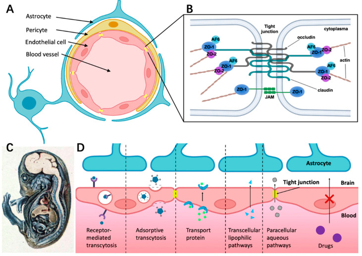
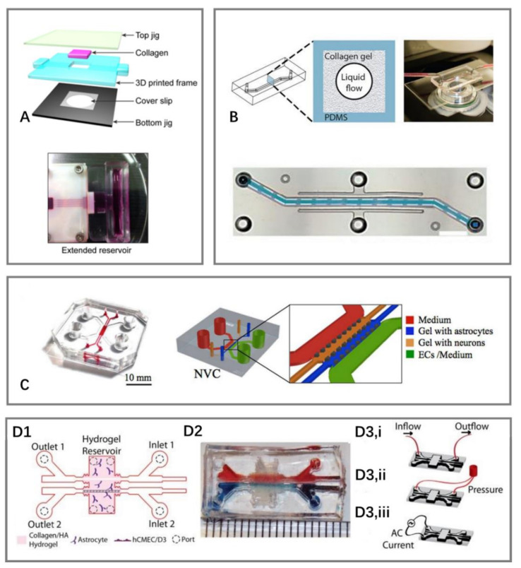
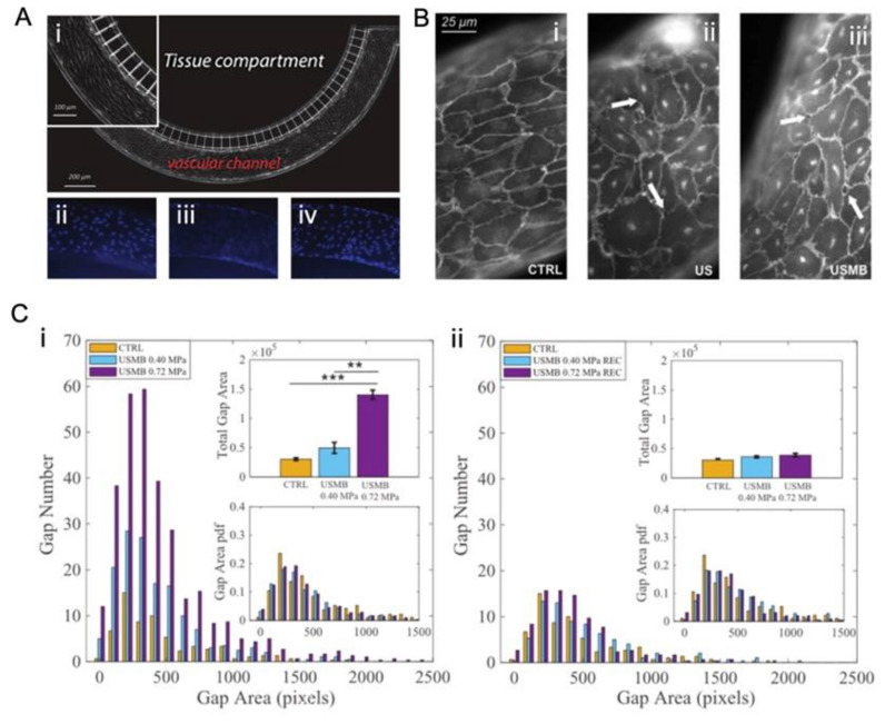
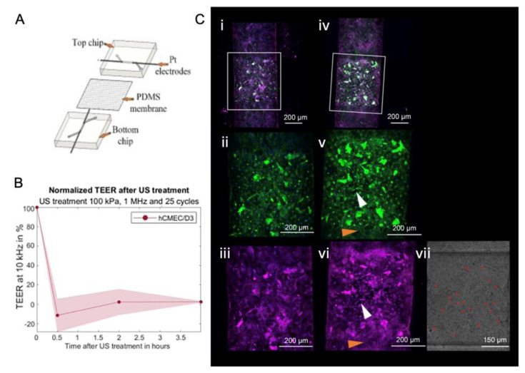
The complex structure of the blood-brain barrier (BBB), which blocks nearly all large biomolecules, hinders drug delivery to the brain and drug assessment, thus decelerating drug development. Conventional in vitro models of BBB cannot mimic some crucial features of BBB in vivo including a shear stress environment and the interaction between different types of cells. There is a great demand for a new in vitro platform of BBB that can be used for drug delivery studies. Compared with in vivo models, an in vitro platform has the merits of low cost, shorter test period, and simplicity of operation. Microfluidic technology and microfabrication are good tools in rebuilding the BBB in vitro. During the past decade, great efforts have been made to improve BBB penetration for drug delivery using biochemical or physical stimuli. In particular, compared with other drug delivery strategies, sonoporation is more attractive due to its minimized systemic exposure, high efficiency, controllability, and reversible manner. BBB on chips (BOC) holds great promise when combined with sonoporation. More details and mechanisms such as trans-endothelial electrical resistance (TEER) measurements and dynamic opening of tight junctions can be figured out when using sonoporation stimulating BOC, which will be of great benefit for drug development. Herein, we discuss the recent advances in BOC and sonoporation for BBB disruption with this in vitro platform.

Keywords: blood–brain barrier; microfluidics; ultrasound-mediated drug delivery.


Conflict of interest statement

The authors declare no conflict of interest.

Figures

Figure 1
Figure 1
The structure of BBB and different transport pathways for substances across the BBB. (A) The BBB consists of endothelial cells (ECs) surrounded by pericyte and astrocyte endfeet. (B) The tight junction is composed of complex and diverse proteins including transmembrane proteins (claudins and occludins), zonula occludens proteins (ZO-I, ZO-II, and ZO-III), and junction-associated molecules (JAMs). (C) Demonstration of BBB hindering trypan blue entering the CNS in guinea pig embryo. The dye infected almost all of the tissue in the body except most of the brain, which indicates that the CNS is a closed compartment separated from the rest of the embryo [41]. (D) Schematic overview of specific transport pathways through the BBB; larger solutes can pass the BBB by receptor-mediated transcytosis and adsorptive transcytosis. Transport protein could cross the BBB through an active transport mechanism. The transcellular lipophilic pathway allows for lipid-soluble agents to pass the BBB. The paracellular pathway enhances the diffusion of water-soluble agents through tight junctions.
Figure 4
Figure 4
Schematic of different 3D models of BOCs. (A) A 3D microfluidic chip for 3D culture, where microchannels were fabricated by microneedles [85]. (B) Microchannels fabricated by viscous fingering to generate lumens in collagen gels [86]. (C) A 3D self-assembled microvascular microfluidic chip [87]. (D) A 3D BBB model that allows for TEER measurement. (D1) Schematic of the structure of a microfluidic device. (D2) Picture of the device with food dye injected into the two channels. (D3) Testing configurations (i) application of fluid flow, (ii) cyclic strain stimulation, and (iii) TEER measurements [90].
Figure 9
Figure 9
A 2D in vitro dynamic system for the study of ultrasound mediated opening of vascular barriers. (A) The model is composed of a tissue compartment and vascular channel [21]. (i) Brightfield image of HUVECs seeded in the vascular channel. The inset highlights the elongation of cells in the direction of flow. (iiiv) Fluorescence images of cell nuclei after DAPI staining. (ii,iv) shows the nuclei of cells adhered on the top and bottom side of the channel, respectively. (iii) focuses on the nuclei of cells adhered on the lateral walls of the channel. (B) Confocal fluorescence images of VE-cadherin showing a region of confluent endothelium cultured at 25 µL/min fluid flow. (i) Untreated sample (CTRL). (ii) The sample exposed only to ultrasound (US). (iii) The sample exposed to ultrasound driven microbubbles (USMBs) with an acoustic pressure of 0.72 MPa, corresponding to a piezo driving voltage of 140 mV. US exposure protocol: duration 30 s, 500 cycles, frequency 1 MHz. Arrows highlight typical intercellular openings [21]. (C) Reversible opening of cell junctions by ultrasound-driven microbubbles in an artificial endothelial layer. Gap number and gap area (i) right after ultrasound irradiation and (ii) 45 min after ultrasound exposure [21].
Figure 10
Figure 10
A sandwich model that mimics the BBB in vitro was employed for the study of the ultrasound mediated opening of vascular barriers. (A) The structure and components of the model. (B) Normalized TEER value changed after focused ultrasound and microbubble treatment (FUS + MB) [127]. (C) Channels with a monolayer of hCMEC/D3 exposed to ultrasound (i–iii) without microbubbles, (ivvi) with microbubbles. FUS + MB treatment of 25 cycles, 1 MHz, and 100 kPa, the red dots in (vii) denote microbubbles, white arrows in (v,vi) designate the same regions of cells that responded to FUS + MB treatment, with ZO-I stained in pink, nuclei stained in blue, and F-actin stained in green [127].
Figure 11
Figure 11
Recent studies on ultrasound-mediated opening of vascular barriers in three-dimensional BOC. (A1) A perfusion-based 3D printable hydrogel vascular model for culturing HUVEC [126]. (A2) Live imaging of endothelial cell–cell junctions under ultrasound exposure [126]. (B1) A 3D model where channels were fabricated by micro-needles [125]. (B2) Transmission electron microscopy for testing conditions of (i) 0.5 W/cm2 ultrasound intensity and 100 μL/min fluid flow and (ii) 1 W/cm2 ultrasound intensity and 10 μL/min fluid flow. (B3) The influence of different flow rates on the cell area reduction under acoustic intensity of 1 W/cm2 [125].
Figure 12
Figure 12
Another two representative studies on the ultrasound-mediated opening of vascular barriers in three-dimensional BOC. (A1) A microvascular chip comprises several channels partitioned by micro-posts [101]. (A2) Effect of different test conditions on cell mortality in the microvasculature [101]. (A3) Microbubbles increased the toxicity of DOX-loaded liposomes to cells under ultrasound exposure [101]. Microvessels were perfused with (i) integrin-targeted liposomes alone or (ii) integrin-targeted liposomes + microbubbles, then washed and treated with ultrasound. Bright field (top) and TRITC fluorescent (bottom) images were taken after 24 h. Black arrows in the bright-field image in panel (ii) show cells extruded from nearby vessels. White arrows in TRITC image in panel (ii) show liposomes that have penetrated the external vessel walls. (B1) A perusable in vitro model for the 3D culture of ECs [37]. (i,ii) Preparation of the microvascular network (MVN). (i) The top half of the MVN: liquid collagen I was injected into the space enclosed by a patterned PDMS stamp and a top acrylic housing. (ii) The bottom half of an MVN: a thin collagen layer was applied on top of a cover glass that sits above the window of a bottom acrylic housing. (iii) After combing the two MVN halves, HUVECs were introduced to the collagen scaffold. (iv) HUVECs attached to the collagen walls overnight and formed a vascular endothelium after 2–3 days of culture. (B2) Assessment of HUVEC permeabilization efficiency under different ultrasound treatment conditions [37]. (B3) Bright field and fluorescence images of the vascular barrier before and after ultrasound-microbubble treatment under acoustic conditions of (i) 1.4 MPa, 500 cycles, 5% duty cycles (DC) and (ii) 0.4 MPa, 1000 cycles, 20% DC. Hoechst (blue) stains HUVEC nuclei; PI (red) stains damaged plasma membranes of cells, which indicates sonoporation or cell death [37].
Figure 13
Figure 13
Schematic of a typical setup used for the ultrasound experiments with BOCs. The chips were placed in the water bath. Ultrasound was generated by the transducer placed at a 45° angle to the chip surface. A stroboscopic light source illuminated the chip while the high-speed camera captured the MB dynamics. The syringe pump perfused microbubbles into the chip.
Figure 2
Figure 2
Representative sandwich models of BOCs. (A-i) Schematic of a popular sandwich design comprises two perpendicular flow channels and electrodes for TEER measurement. (A-ii) The assembled μBBB chip as shown in panel (i). (A-iii) An enlarged view of the perpendicular flow channels and electrodes [4]. (B-i) Schematic of a multiplexed chip with eight parallel channels separated by a porous PDMS membrane. (B-ii) Top view of the two-layer chip design. (B-iii) The result of creating eight different conditions in the fabricated two-layer chip [31]. (C-i) Fabricated device of a pump-free microfluidic chip. Red dye was used to visualize the microchannels, neuronal compartments, and reservoirs. (C-ii) Schematic for the components of the device: a bottom perfusion layer with microchannels and bottom electrodes; a middle chamber layer that forms reservoirs and the neuronal chamber; a top lid layer with top electrodes, which covers the neuronal chamber and the reservoirs to minimize fluid evaporation; a cell insert part made from two silicone sheets and a sandwiched porous polycarbonate membrane. The cell insert part was assembled between the bottom and the middle layers. (C-iii) Side view of the device structure, including fluid chamber, microchannels, electrodes connected to a Millicell-ERS Volt-Ohm Meter and the co-cultural orientation of BBB cells [39].
Figure 3
Figure 3
Schematic of different 2D models of BOCs. (A-i) The mask design of a microfluidic chip consisting of circular vascular channels and tissue compartment. (A-ii) The fabricated BOC on a microscope glass slide with plastic tubing and individual vascular channels and the tissue compartment stained (dark blue). (A-iii) Schematic illustration of cell culture in the BOC showing the endothelial cell lining on the walls of the vascular channel (blue), astrocytes contained in the tissue compartment (red), and their contact through the porous interface [74]. (B) Another design of 2D BOC with the apical and basolateral sides separated by 3 μm gaps formed by microfabricated pillars. Apical side contains endothelial cells while the basolateral side contains astrocyte conditioned media [75]. (C) A 2D microfluidic device for high-throughput drug assessment. (i) Top view of the fabricated microfluidic chip, which contains eight independent units; (ii) Each unit consists of three main channels. For each channel, the width and height is 500 μm and 100 μm, respectively, and the length for the parallel part is 2 cm. (iii) An enlarged view of the channel structure in the parallel part. An array of microchannels (3 μm in width) is in between the brain channel and the blood channel. Another array of microchannels (50 μm in width) is in between the brain and the media channels [80].
Figure 5
Figure 5
Different means to evaluate the BBB integrity. (A) TEER measurement in a BOC device, where copper electrode wiring is connected to the voltohmmeter via an electrode adapter [4]. (B) Immunofluorescence micrographs of the human brain endothelium cultured on-chip for 3 days, showing high expression levels of ZO-1, claudin-5, PECAM-1, GLUT-1, and P-glycoprotein (bar, 20 µm) [65]. (C) Electron micrograph of human brain microvascular endothelium after 3 days of culture in the BBB chip. The presence of well-formed tight junctions (top, pointed by arrows) and adherent junctions (bottom, indicated by arrows) are highlighted [65]. (D) Confocal fluorescence imaging of VE-cadherin for a portion of the endothelium after US exposure with the presence of MBs [21]. (E-i) Permeability of Texas Red dextran (40 kDa) from the vascular channel to the tissue compartment in the cell-free BOC after 5 min, 15 min, 30 min, 60 min. and 120 min from the start of flow in the vascular channel. (E-ii) Quantification of the normalized intensity of the dextran in the tissue compartment as shown in (E-i). The intensity increased linearly with time [74].
Figure 6
Figure 6
Microbubbles exhibit two states (stable cavitation and inertial cavitation) under different acoustic pressures, leading to different bioeffects.
Figure 7
Figure 7
Representative studies for BBB opening by ultrasound-driven microbubbles in vivo. (A) (i) In vivo PET/CT images of 64Cu-CuNCs without focused ultrasound (FUS) treatment and under 0.28 and 0.61 MPa FUS pressure in WT mice at 24 h post intravenous injection. (ii) Quantitative analysis of 64Cu-CuNC uptake in FUS-treated left pons and nontreated right pons of WT mice under 0.28, 0.61, 0.72, and 0.85 MPa FUS pressures as well as in the pons without FUS treatment in WT mice. (iii) Uptake ratios of the treated sites vs. nontreated sites of the FUS-treated mice under different pressures (*** p < 0.001, **** p < 0.0001, n = 4−5) [13]. (B) Coronal MR image after intravenous injection of gadodiamide 1 h after sonication, showing the presence of gadodiamide in the brain parenchyma confirming the local disruption of BBB. Two opening sites under different ultrasound treatment are circled (purple circle 0.3 MPa and orange circle 0.45 MPa). 6 days after sonication, coronal MR image confirming that the BBB is closed and the procedure is reversible [113]. (C) Brain CT images (gadolinium enhancement in T1-weighted) of patients 1–4 immediately after the BBB opening procedure (BBB01). The BBB opening was closed after 24 h (stage 1) in patients 1, 3, and 4 (BBB01-24 h) and in patient 2 on the seventh day of MRI follow-up (BBB01-7d). For stage 2 treatment, the BBB was closed in patients 1 and 2 after 24 h and in patients 3 and 4 in the following MRI study on day 7 (BBB02-7d) [116].
Figure 8
Figure 8
Different kinds of in vitro static systems employed for the study of ultrasound mediated opening of the BBB. (A) Ultrasound-driven microbubbles stimulate ECs in the Transwell model [120]. (B) Ultrasound stimulates HUVEC in the monolayer culture model [122].

References

    1. Alzheimer’s Association 2020 Alzheimer’s Disease Facts and Figures. Alzheimer’s Dement. 2020;14:367–429. doi: 10.1002/alz.12068. - DOI
    1. Pardridge W.M. Blood-brain barrier drug targeting: The future of brain drug development. Mol. Interv. 2003;3:90. doi: 10.1124/mi.3.2.90. - DOI - PubMed
    1. Weidenfeller C., Svendsen C.N., Shusta E.V. Differentiating embryonic neural progenitor cells induce blood–brain barrier properties. J. Neurochem. 2007;101:555–565. doi: 10.1111/j.1471-4159.2006.04394.x. - DOI - PMC - PubMed
    1. Booth R., Kim H. Characterization of a microfluidic in vitro model of the blood-brain barrier (μBBB) Lab Chip. 2012;12:1784–1792. doi: 10.1039/c2lc40094d. - DOI - PubMed
    1. Aday S., Cecchelli R., Hallier-Vanuxeem D., Dehouck M.P., Ferreira L. Stem Cell-Based Human Blood-Brain Barrier Models for Drug Discovery and Delivery. Trends Biotechnol. 2016;34:382–393. doi: 10.1016/j.tibtech.2016.01.001. - DOI - PubMed

LinkOut - more resources