Review
. 2022 Nov 24:10:rbac094.
doi: 10.1093/rb/rbac094. eCollection 2023.

Functional engineering strategies of 3D printed implants for hard tissue replacement

Affiliations
Review

Functional engineering strategies of 3D printed implants for hard tissue replacement

Cen Chen et al. Regen Biomater. .

Abstract

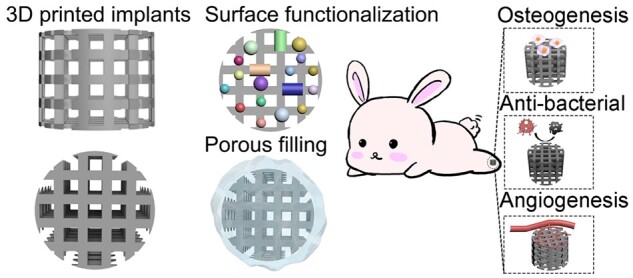
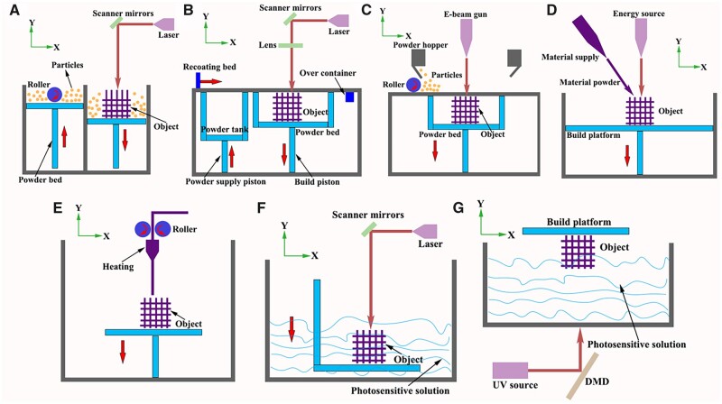
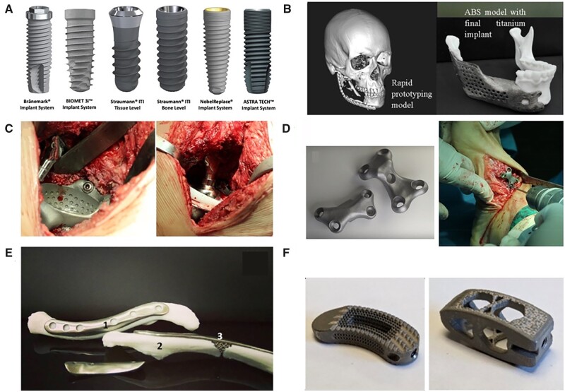
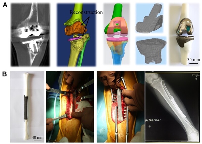
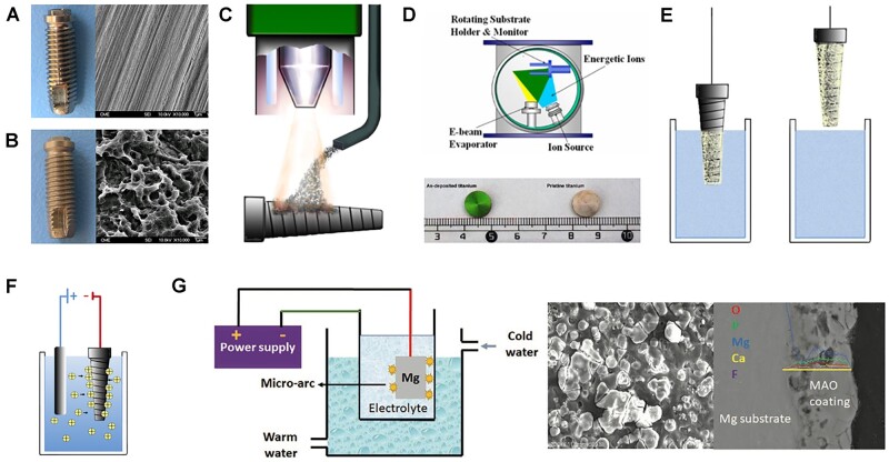
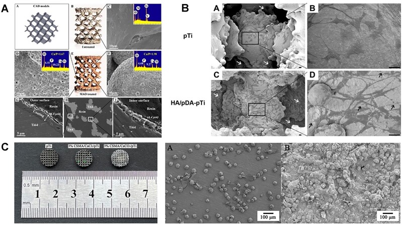
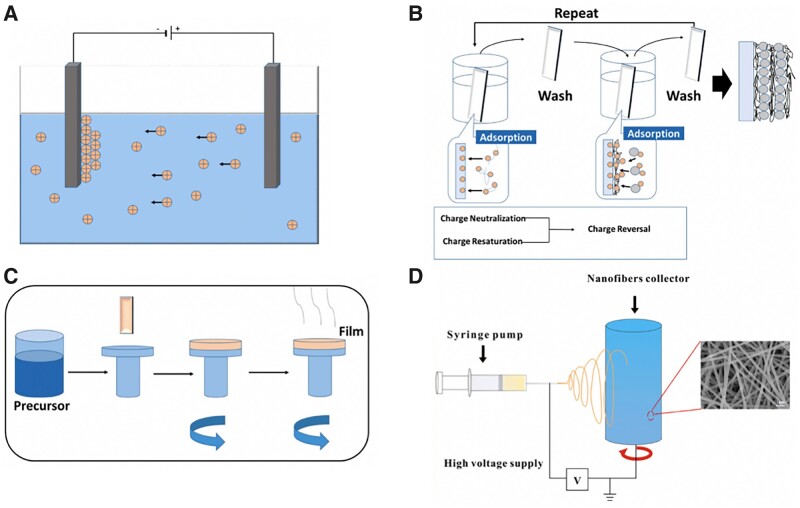
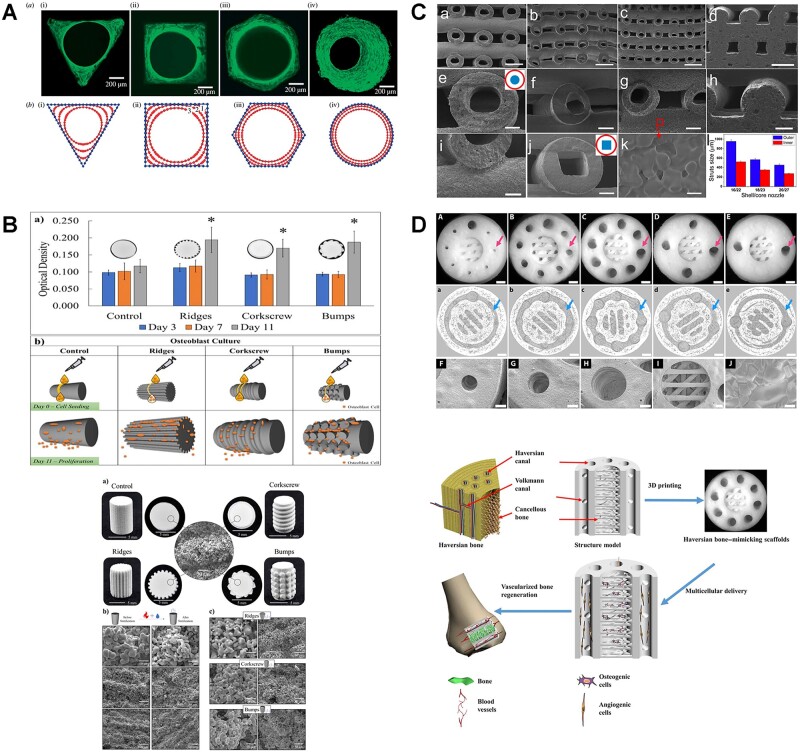
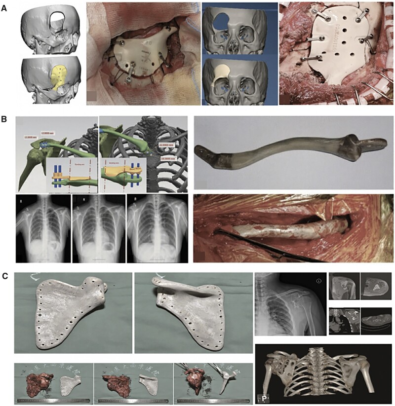
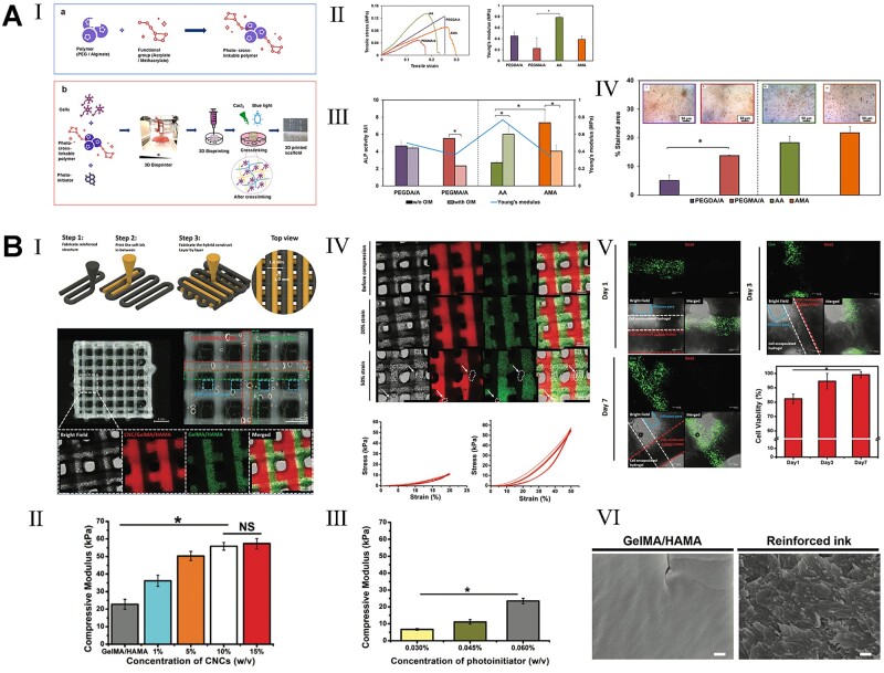
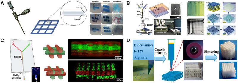
Three-dimensional printing technology with the rapid development of printing materials are widely recognized as a promising way to fabricate bioartificial bone tissues. In consideration of the disadvantages of bone substitutes, including poor mechanical properties, lack of vascularization and insufficient osteointegration, functional modification strategies can provide multiple functions and desired characteristics of printing materials, enhance their physicochemical and biological properties in bone tissue engineering. Thus, this review focuses on the advances of functional engineering strategies for 3D printed biomaterials in hard tissue replacement. It is structured as introducing 3D printing technologies, properties of printing materials (metals, ceramics and polymers) and typical functional engineering strategies utilized in the application of bone, cartilage and joint regeneration.

Keywords: 3D printing; additive manufacturing; bone regeneration; functional engineering; hard tissue replacement.


Figures

None
Graphical abstract
Figure 1.
Figure 1.
Schematic illustration of commonly used 3D printing technologies [12, 21, 32, 33, 37–39] (A: SLS; B: SLM; C: EBM; D: DED; E: FDM; F: SLA; G: DLP).
Figure 2.
Figure 2.
The clinical application of Ti-based implants [78–80]. (A: Commercially available dental implants. Reproduced with permission from Ref. [80] Copyright 2020 Japanese Society for Dental Materials and Devices. B: The anatomic design of the mandibular implant with a lattice structure. C: Hip replacement of Ti6Al4V implant using EBM technology; D: patient-specific Ti6Al4V implants in foot osteotomy; E: 3D printed Ti implant with lattice structured insert by TechMed Technion for clavicular reconstruction. Reproduced with permission from Ref. [78] Copyright 2018 Springer Nature. F: Activated Ti interbody cages. Reproduced with permission from Ref. [79] Copyright 2021 Springer Nature.).
Figure 3.
Figure 3.
The clinical application for tantalum implants [92]. (A: EBM-fabricated ta lattice implants for hip reconstruction; B: EBM-fabricated ta fibula lattice implants.) reproduced with permission from Ref. [92] Copyright 2020 Spring Nature.
Figure 4.
Figure 4.
Representative examples of surface modification strategies [107, 153]. (A: Machined surface of Ti implant. B: Sand-blasted and then acid-etched implant. C: Plasma-spraying, to form an oxide film on the Ti surface and allows ceramic coating formation. D: IBAD, able to prepare bio-coatings with considerably higher adhesion strength. E: Dipping, sol–gel and biomimetic coating, known as simple operation and cost-effective methods. F: EPD, utilizing two electrodes to induce the migration of particles in solution towards the surface to be coated. Reproduced with permission from Ref. [107] Copyright 2020 John Wiley and Son. G: MAO treatment of Mg-based metals to form a CaPs coating. Reproduced with permission from Ref. [153] Copyright 2017 American Chemical Society).
Figure 5.
Figure 5.
Ca-based coating for the 3D printed porous Ti-based implants (especially for internal surface) [180, 181, 183]. (A: the porous Ti6Al4V scaffold after MAO treatment displayed homogeneous layer of microporous titanium oxides coating containing a significant amount of Ca and P. The thickness of coating at the inner and outer surface were 4.4 and 4.8 μm. Reproduced with permission from Ref. [180] Copyright 2016 American Chemical Society. B: HA coating was clearly loaded on the inner surfaces of the scaffold with pre-deposited pDA film. Cells were favorably adhered on the inner surfaces (white arrows) with lamellipodia extensions (black arrow) after HA/pDA immobilization. Reproduced with permission from Ref. [181] Copyright 2020 American Chemical Society. C: The observation of 3D printed porous titanium filled with mineralized chitosan hydrogel. CaCO3 mineral layer grew inside hydrogels and wrapped up their polymer networks to provide a strong bonding between hydrogel and porous Ti scaffold.)
Figure 6.
Figure 6.
Polymeric coating strategies on metallic implants [185]. (A: EPD; B: layer-by-layer assembly; C: spinning coating; D: electrospinning) reproduced with permission from Ref. [185] Copyright 2021 Elsevier).
Figure 7.
Figure 7.
Representative examples of structural modification of bioceramics implants [243–246]. (A: Hydroxyapatite channels with controlled cross-sections of different geometries (triangular, square, hexagonal and circular) reproduced with permission from Ref. [243] Copyright 2008 the Royal Society. B: Surface topography modification via 3D printing can increase surface area to support enhanced biological response without compromising mechanical properties. Reproduced with permission from Ref. [244] Copyright 2021 Elsevier. C: Hollow-struts-packed (HSP) bioceramic scaffolds with designed macropores and multioriented hollow channels via a modified coaxial 3D printing strategy. Reproduced with permission from Ref. [245] Copyright 2015 American Chemical Society. D: A haversian bone-mimicking scaffold prepared via DLP printing reproduced with permission from Ref. [246] Copyright 2020 American Association for the advancement of science.)
Figure 8.
Figure 8.
The clinical application for polymeric implants [304–306]. (A: 3D printed PEEK for complex craniofacial defect. Reproduced with permission from Ref. [304] Copyright 2021 Wolter’s Kluwer Health. Inc. B: 3D PEEK implant designed, molded and inserted into defect area in subtotal clavicle reconstruction. Reproduced with permission from Ref. [305] Copyright 2021 Wolter’s Kluwer Health. Inc. C: PEEK prosthesis for scapular reconstruction. PEEK prosthesis was in normal position from X-ray image after tumor resection. Reproduced with permission from Ref. [306] Copyright 2018 Elsevier.)
Figure 9.
Figure 9.
Mechanical reinforcement of composite polymers for 3D printing [329, 339]. (A: I. Overall 3D bioprinting process to fabricate functional PEG diacrylate (PEGDA) or PEG dimethacrylate (PEGMA)-Alg acrylate (AA) or alg ormethacrylate (AMA) crosslinked scaffolds. II. Stress-strain curve and young’s modulus (MPa) value of different hydrogels indicated the functionalized PEG and alginate gels exhibited high mechanical strength compared with natural materials. III. The ALP activities of functionalized hydrogels demonstrated the favorable osteogenic effects with any additive agents. Reproduced with permission from Ref. [339] Copyright 2021 Elsevier. B: I. Illustration of the hybrid printing procedure and the observation of the hybrid printed construct (the hybrid printed constructs were fabricated using the two hydrogel inks: cellulose nanocrystals (CNCs)-reinforced GelMA/HLAMA and GelMA/HLAMA inks, which were defined in the optical microscopic image by red dotted lines and green dotted lines, respectively.) II–III. Compression test for the optimal concentration of GelMA/HLAMA, reinforced hydrogel and photoinitiator. IV. Mechanical results of hybrid printed construct after cyclic compression (structural integrity was retained after 10 cycles of compression with 20% strain. After 10 cycles of compression with 50% strain, the structural defects appeared as marked by the white arrow and dot line). V. Cells remained high viability of 82.4 ± 3.3% at day 1 and reached to 99.1 ± 2.2% at day 7. VI. SEM observation of GelMA/HLAMA ink. Reproduced with permission from Ref. [329] Copyright 2020 John Wiley and Sons.)
Figure 10.
Figure 10.
Multi-material bioprinting based on microextrusion technologies with multiple printing-heads [245, 357–359]. (A: Coaxial nozzles were design for gird construct with inner/outer layers. Reproduced with permission from Ref. [357] Copyright 2020 Wolters Kluwer. B: The design of microfluidic printheads with multiple inlets and an outlet, and the color-coded heterogenous construct. Reproduce with the permission from Ref. [358] Copyright Whioce Publishing. C: Microfluidic system (‘Y’ shaped channel) was used to flow two separate bioinks containing red and green fluorescent beads that through a single extruder. Reproduced with permission from Ref. [359] Copyright 2015 John Wiley and Sons. D: Bioceramic powders with F-127 solution and alginate were printed by extrusion printer with coaxial printing nozzle, followed by sintering to achieve mechanically stable construct. Reproduced with permission from Ref. [245] Copyright 2015 American Chemical Society.)

Similar articles

Cited by

References

    1. Roseti L, Parisi V, Petretta M, Cavallo C, Desando G, Bartolotti I, Grigolo B.. Scaffolds for bone tissue engineering: state of the art and new perspectives. Mater Sci Eng C Mater Biol Appl 2017;78:1246–62. - PubMed
    1. Florencio-Silva R, Sasso GRdS, Sasso-Cerri E, Simões MJ, Cerri PS.. Biology of bone tissue: structure, function, and factors that influence bone cells. Biomed Res Int 2015;2015:421746. - PMC - PubMed
    1. Feng X, McDonald JM.. Disorders of bone remodeling. Annu Rev Pathol 2011;6:121–45. - PMC - PubMed
    1. Marie P. Physiology of bone tissue. Immuno-Anal Biol Spec 1992;7:17–24.
    1. Turnbull G, Clarke J, Picard F, Riches P, Jia L, Han F, Li B, Shu W.. 3D bioactive composite scaffolds for bone tissue engineering. Bioact Mater 2018;3:278–314. - PMC - PubMed