

Reconstruction of massive bone defects after femoral tumor resection using two new-designed 3D-printed intercalary prostheses: a clinical analytic study with the cooperative utilization of multiple technologies
- PMID: 36698116
- PMCID: PMC9875495
- DOI: 10.1186/s12891-023-06171-w
Reconstruction of massive bone defects after femoral tumor resection using two new-designed 3D-printed intercalary prostheses: a clinical analytic study with the cooperative utilization of multiple technologies
Abstract
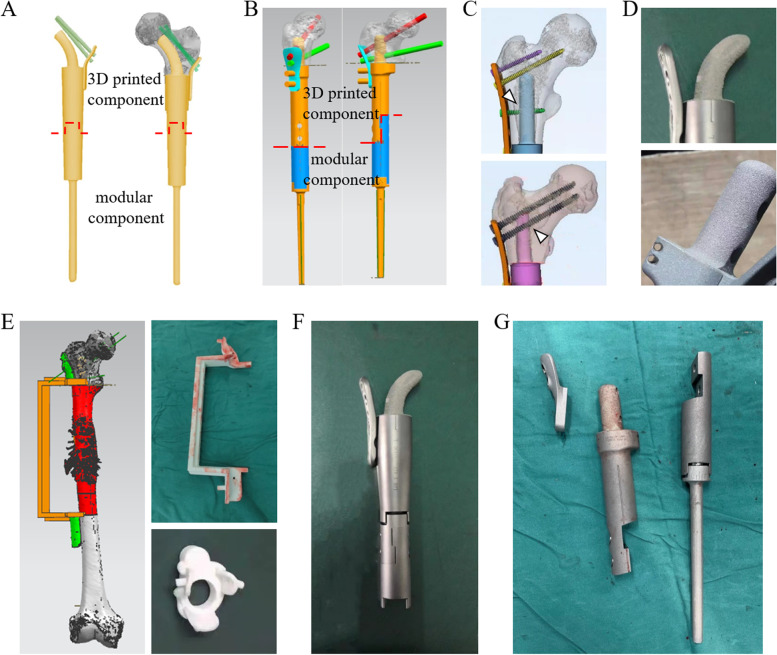
Background: To reconstruct massive bone defects of the femoral diaphysis and proximal end with limited bilateral cortical bone after joint-preserving musculoskeletal tumor resections, two novel 3D-printed customized intercalary femoral prostheses were applied.
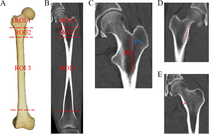
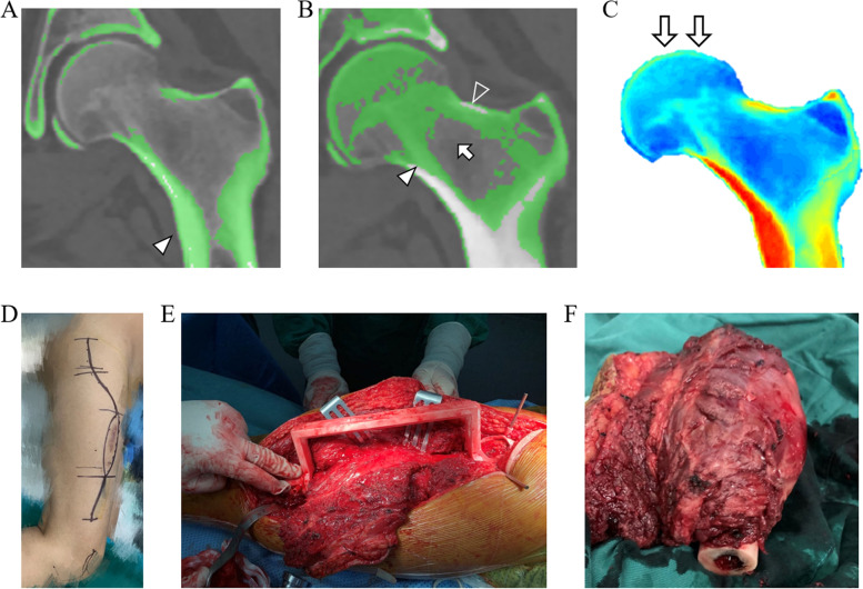
Methods: A series of nine patients with malignancies who received these novel 3D-printed prostheses were retrospectively studied between July 2018 and November 2021. The proximal and diaphyseal femur was divided into three regions of interest (ROIs) according to anatomic landmarks, and anatomic measurements were conducted on 50 computed tomography images showing normal femurs. Based on the individual implant-involved ROIs, osteotomy level, and anatomical and biomechanical features, two alternative 3D-printed prostheses were designed. In each patient, Hounsfield Unit (HU) value thresholding and finite element analysis were conducted to identify the bone trabecula and calcar femorale and to determine the stress distribution, respectively. We described the characteristics of each prosthesis and surgical procedure and recorded the intraoperative data. All patients underwent regular postoperative follow-up, in which the clinical, functional and radiographical outcomes were evaluated.
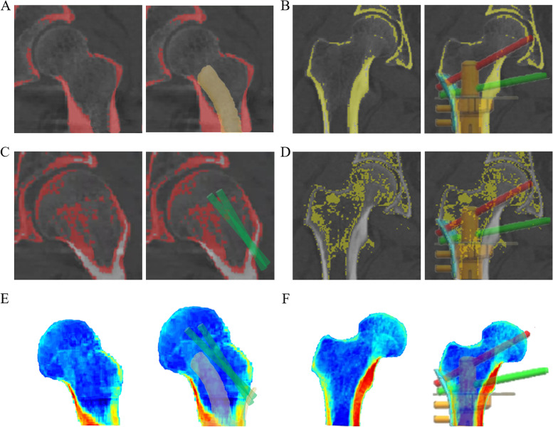
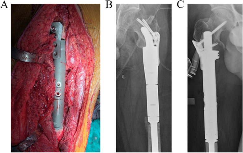
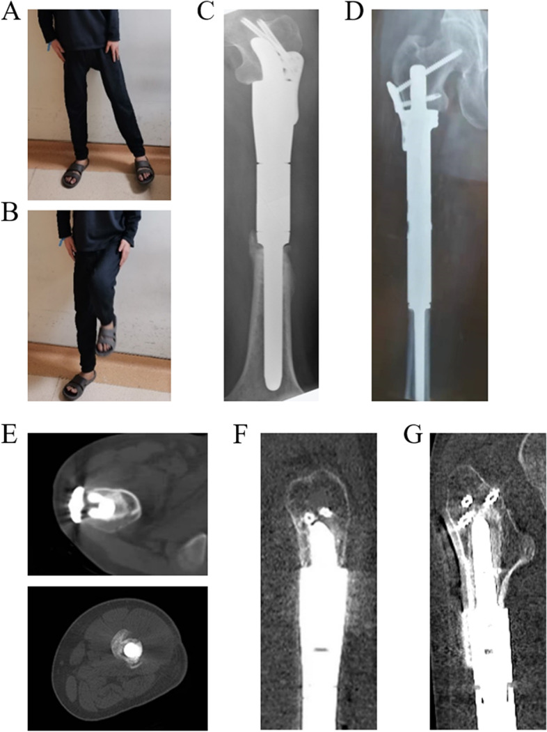
Results: With the ROI division and radiographic measurements, insufficient bilateral cortical bones for anchoring the traditional stem were verified in the normal proximal femur. Therefore, two 3D-printed intercalary endoprostheses, a Type A prosthesis with a proximal curved stem and a Type B prosthesis with a proximal anchorage-slot and corresponding locking screws, were designed. Based on HU value thresholding and finite element analysis, the 3D-printed proximal stems in all prostheses maximally preserved the trabecular bone and calcar femorale and optimized the biomechanical distribution, as did the proximal screws. With the 3D-printed osteotomy guide plates and reaming guide plates, all patients underwent the operation uneventfully with a satisfactory duration (325.00 ± 62.60 min) and bleeding volume (922.22 ± 222.36 ml). In the follow-up, Harris Hip and Musculoskeletal Tumor Society scores were ameliorated after surgery (P < 0.001 and P < 0.001, respectively), reliable bone ingrowth was observed, and no major complications occurred.
Conclusions: Two novel 3D-printed femoral intercalary prostheses, which achieved acceptable overall postoperative outcomes, were used as appropriate alternatives for oncologic patients with massive bone defects and limited residual bone and increased the opportunities for joint-preserving tumor resection. Several scientific methodologies utilized in this study may promote the clinical design proposals of 3D-printed implants.
Keywords: 3D printing; Bone tumor resection; Femur; Intercalary prosthesis; Joint-preserving surgery; Reconstruction.
© 2023. The Author(s).
Conflict of interest statement
The authors declare no conflicts of interest.
Figures
Similar articles
-
Utilization of 3D-Printed Customized Uncemented Stem Prostheses for Revision of Aseptic Loosening in the Distal Femoral Cemented Prostheses: Case Series and Literature Review.Orthop Surg. 2025 Mar;17(3):801-813. doi: 10.1111/os.14331. Epub 2024 Dec 23. Orthop Surg. 2025. PMID: 39711270 Free PMC article. Review.
-
[Mid-term effectiveness of hip preservation in the reconstruction of ultrashort bone segments in the proximal femur with three-dimensional printed customized cementless intercalary endoprosthesis with an intra-neck curved stem].Zhongguo Xiu Fu Chong Jian Wai Ke Za Zhi. 2023 Aug 15;37(8):970-977. doi: 10.7507/1002-1892.202304057. Zhongguo Xiu Fu Chong Jian Wai Ke Za Zhi. 2023. PMID: 37586797 Free PMC article. Chinese.
-
Hip reconstruction using a customized intercalary prosthesis with the rhino horn-designed uncemented stem for ultrashort proximal femur segments following tumor resection: a combined biomechanical and clinical study.BMC Musculoskelet Disord. 2022 Sep 8;23(1):852. doi: 10.1186/s12891-022-05805-9. BMC Musculoskelet Disord. 2022. PMID: 36076197 Free PMC article.
-
Outcomes of a Modular Intercalary Endoprosthesis as Treatment for Segmental Defects of the Femur, Tibia, and Humerus.Clin Orthop Relat Res. 2016 Feb;474(2):539-48. doi: 10.1007/s11999-015-4588-z. Clin Orthop Relat Res. 2016. PMID: 26475032 Free PMC article.
-
[Research progress in repair and reconstruction of tumor-related bone defects in proximal femur].Zhongguo Xiu Fu Chong Jian Wai Ke Za Zhi. 2024 Oct 15;38(10):1269-1275. doi: 10.7507/1002-1892.202404018. Zhongguo Xiu Fu Chong Jian Wai Ke Za Zhi. 2024. PMID: 39433503 Free PMC article. Review. Chinese.
Cited by
-
Utilization of 3D-Printed Customized Uncemented Stem Prostheses for Revision of Aseptic Loosening in the Distal Femoral Cemented Prostheses: Case Series and Literature Review.Orthop Surg. 2025 Mar;17(3):801-813. doi: 10.1111/os.14331. Epub 2024 Dec 23. Orthop Surg. 2025. PMID: 39711270 Free PMC article. Review.
-
Innovations in three-dimensional-printed individualized bone prosthesis materials: revolutionizing orthopedic surgery: a review.Int J Surg. 2024 Oct 1;110(10):6748-6762. doi: 10.1097/JS9.0000000000001842. Int J Surg. 2024. PMID: 38905508 Free PMC article. Review.
-
Uncemented Customized Hollow Stems in Tumor Endoprosthetic Replacement-A Good Opportunity to Protect the Adjacent Joint in Children?J Pers Med. 2024 Aug 29;14(9):919. doi: 10.3390/jpm14090919. J Pers Med. 2024. PMID: 39338173 Free PMC article.
-
3D-printed custom-made short stem with porous structure for fixation of massive endoprosthesis in joint-preserving reconstruction after tumor resection.J Orthop Surg Res. 2023 Jun 29;18(1):468. doi: 10.1186/s13018-023-03954-8. J Orthop Surg Res. 2023. PMID: 37386639 Free PMC article.
-
Biomechanical comparison of a novel triangular fixation stem and a conventional fixation stem in a model of a prosthesis for ultrashort residual proximal femur reconstruction: a finite element analysis study.BMC Musculoskelet Disord. 2025 Jun 7;26(1):570. doi: 10.1186/s12891-025-08805-7. BMC Musculoskelet Disord. 2025. PMID: 40483446 Free PMC article.
References
MeSH terms
LinkOut - more resources
Full Text Sources
Medical
