. 2023 Jan 30;13(1):1636.
doi: 10.1038/s41598-023-28769-9.

Modeling of intracranial tumor treating fields for the treatment of complex high-grade gliomas

Affiliations

Modeling of intracranial tumor treating fields for the treatment of complex high-grade gliomas

David J Segar et al. Sci Rep. .

Erratum in

Abstract

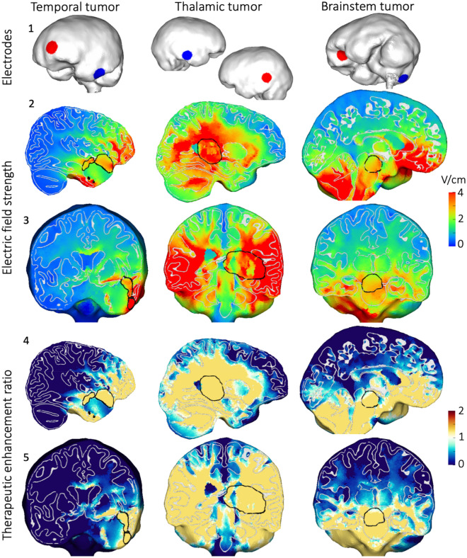
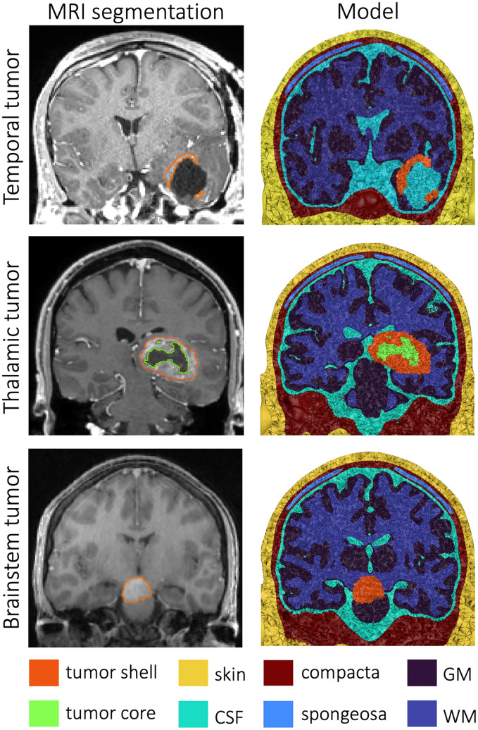
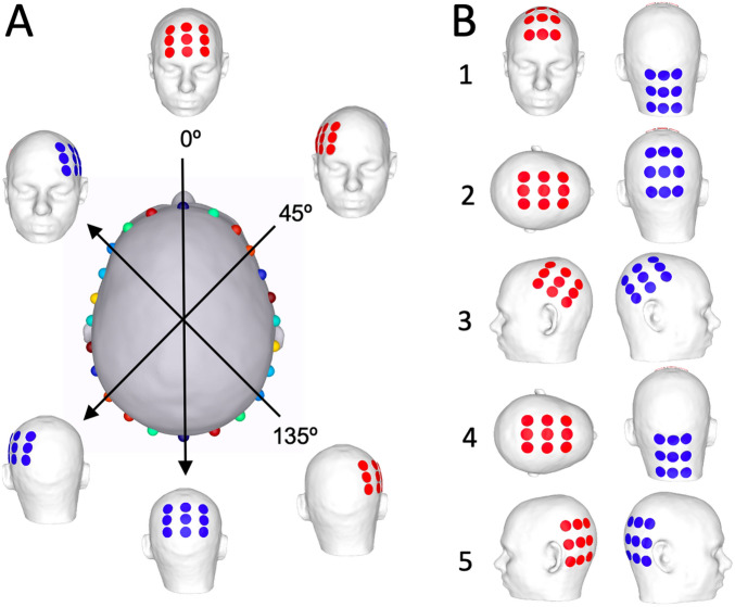
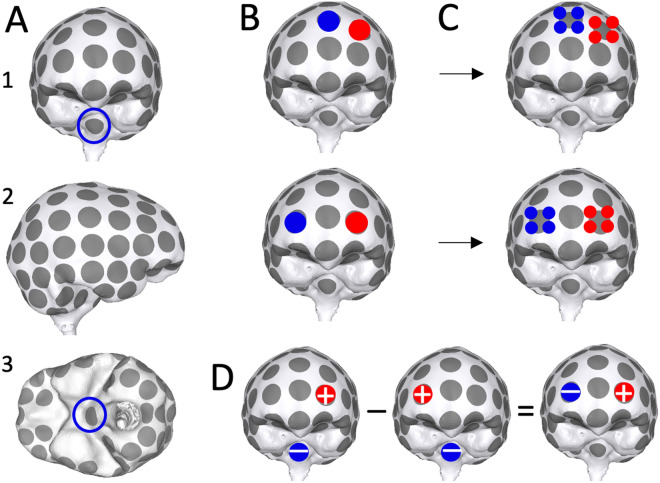
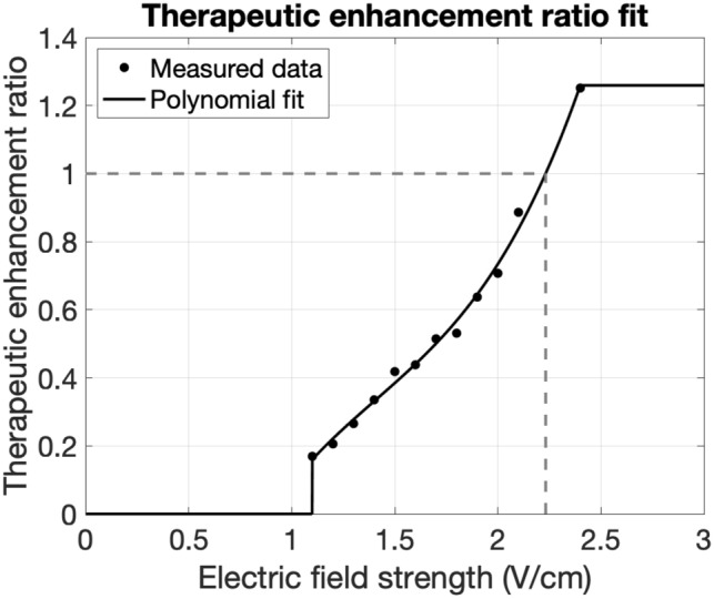
Increasing the intensity of tumor treating fields (TTF) within a tumor bed improves clinical efficacy, but reaching sufficiently high field intensities to achieve growth arrest remains challenging due in part to the insulating nature of the cranium. Using MRI-derived finite element models (FEMs) and simulations, we optimized an exhaustive set of intracranial electrode locations to obtain maximum TTF intensities in three clinically challenging high-grade glioma (HGG) cases (i.e., thalamic, left temporal, brainstem). Electric field strengths were converted into therapeutic enhancement ratios (TER) to evaluate the predicted impact of stimulation on tumor growth. Concurrently, conventional transcranial configurations were simulated/optimized for comparison. Optimized intracranial TTF were able to achieve field strengths that have previously been shown capable of inducing complete growth arrest, in 98-100% of the tumor volumes using only 0.54-0.64 A current. The reconceptualization of TTF as a targeted, intracranial therapy has the potential to provide a meaningful survival benefit to patients with HGG and other brain tumors, including those in surgically challenging, deep, or anatomically eloquent locations which may preclude surgical resection. Accordingly, such an approach may ultimately represent a paradigm shift in the use of TTFs for the treatment of brain cancer.


Conflict of interest statement

DJS is an officer and board member with equity in Saturn5 Corporation. JDB has an equity position in Treovir LLC and is a member of the POCKiT Diagnostics Board of Scientific Advisors. GKF is supported by Eli Lilly and Company and Pfizer through contracts to UAB. The remaining authors declare no pertinent conflicts of interest.

Figures

Figure 1
Figure 1
TER optimization curves. Each curve indicates the amount of current needed to achieve a TER greater than 0 (gray) or 1 (black) in a percentage of the ROI for transcranial (dashed) and intracranial (solid) TTF for three tumor cases. Horizontal lines indicate the current level conventionally used for transcranial TTF (0.9 A). Crosses indicate configurations that were selected as the optimal results, which are visualized in Fig. 2 and Supplementary Fig. S3.
Figure 2
Figure 2
Optimal intracranial configurations and results. The optimal configurations (row 1) produced electric fields in the brain (rows 2–3: sagittal and coronal views) that achieved a TER in the tumor (rows 4–5: identical views). Results are shown on cuts through the center of the tumor, which is outlined in black. Gray and white matter boundaries are outlined in white. The selected configurations achieved TER>1 in at least 90% of the ROI (marked in Fig. 1; details in Supplementary Table S2).
Figure 3
Figure 3
Tumor head models. For three tumor cases, tumors were segmented from patient MRIs (left) and the segmentation masks (outlines on the MRIs) were mapped onto the base model, resulting in three head models (right).
Figure 4
Figure 4
Transcranial electrode design. (A) The center image shows the transcranial model from above. We started on the line marked 0°; two patches were centered on the locations indicated by the blue spheres, resulting in the model shown at the top (anterior view) and bottom (posterior view) of the line. This pair of patches was then rotated around the vertical axis; spheres on the center image indicate the patch centers. Examples are shown at 0°, 45° and 135°. (B) Five transcranial configurations were based on prior studies.
Figure 5
Figure 5
Intracranial electrode design. (A) Anterior (1), right (2) and inferior (3) views of the intracranial model; 101 electrodes were spread across the CSF surface and a reference (necessary for simulations, but not clinical practice) was placed on the brainstem (marked with blue circles). Supplementary Fig. S1 presents additional views. (B) Two examples of 2-electrode configurations. (C) Each electrode in the simulated two-electrode configurations can be replaced with small-electrode arrays. (D) Electric fields for each electrode pair were calculated by simulating each electrode with the reference (first two images), and then taking the difference of the two (result on the right).
Figure 6
Figure 6
Fit of in vitro TER data. Black dots are a reproduction of data from Kirson et al. who applied TTF to malignant glioma cell cultures and measured TER values. We fit a polynomial (black line) to the experimental data and capped values outside the reported range. TER=1 indicates complete growth arrest, which happens at E = 2.23 V/cm (dashed line). This differs slightly from prior work (2.25 V/cm) due to a small difference in the fit.

References

    1. Mun EJ, Babiker HM, Weinberg U, Kirson ED, Von Hoff DD. Tumor-treating fields: A fourth modality in cancer treatment. Clin. Cancer Res. Off. J. Am. Assoc. Cancer Res. 2018;24(2):266–275. doi: 10.1158/1078-0432.CCR-17-1117. - DOI - PubMed
    1. Dolecek TA, Propp JM, Stroup NE, Kruchko C. CBTRUS statistical report: Primary brain and central nervous system tumors diagnosed in the United States in 2005–2009. Neuro-Oncol. 2012;14(Suppl 5):v1–v49. doi: 10.1093/neuonc/nos218. - DOI - PMC - PubMed
    1. Stupp R, Kanner A, Engelhard H, et al. A prospective, randomized, open-label, phase III clinical trial of NovoTTF-100A versus best standard of care chemotherapy in patients with recurrent glioblastoma. J. Clin. Oncol. 2010;28(18 suppl):LBA2007. doi: 10.1200/jco.2010.28.18_suppl.lba2007. - DOI
    1. Stupp R, Wong ET, Kanner AA, et al. NovoTTF-100A versus physician’s choice chemotherapy in recurrent glioblastoma: A randomised phase III trial of a novel treatment modality. Eur. J. Cancer Oxf. Engl. 1990. 2012;48(14):2192–2202. doi: 10.1016/j.ejca.2012.04.011. - DOI - PubMed
    1. Stupp R, Taillibert S, Kanner AA, et al. Maintenance therapy with tumor-treating fields plus temozolomide vs temozolomide alone for glioblastoma: A randomized clinical trial. JAMA. 2015;314(23):2535–2543. doi: 10.1001/jama.2015.16669. - DOI - PubMed