. 2023 Feb 1;14(1):404.
doi: 10.1038/s41467-023-36030-0.

Grain refinement in titanium prevents low temperature oxygen embrittlement

Affiliations

Grain refinement in titanium prevents low temperature oxygen embrittlement

Yan Chong et al. Nat Commun. .

Abstract

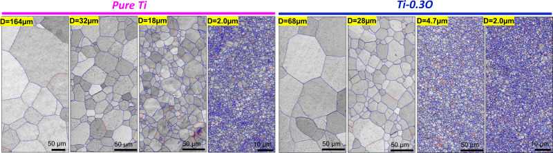
Interstitial oxygen embrittles titanium, particularly at cryogenic temperatures, which necessitates a stringent control of oxygen content in fabricating titanium and its alloys. Here, we propose a structural strategy, via grain refinement, to alleviate this problem. Compared to a coarse-grained counterpart that is extremely brittle at 77 K, the uniform elongation of an ultrafine-grained (UFG) microstructure (grain size ~ 2.0 µm) in Ti-0.3wt.%O is successfully increased by an order of magnitude, maintaining an ultrahigh yield strength inherent to the UFG microstructure. This unique strength-ductility synergy in UFG Ti-0.3wt.%O is achieved via the combined effects of diluted grain boundary segregation of oxygen that helps to improve the grain boundary cohesive energy and enhanced <c + a> dislocation activities that contribute to the excellent strain hardening ability. The present strategy will not only boost the potential applications of high strength Ti-O alloys at low temperatures, but can also be applied to other alloy systems, where interstitial solution hardening results into an undesirable loss of ductility.


Conflict of interest statement

The authors declare no competing interests.

Figures

Fig. 1
Fig. 1. Initial microstructures of pure Ti and Ti-0.3O alloys.
Representative grain boundary maps (blue lines: high-angle grain boundaries with misorientation angle, θ > 15°, red lines: low-angle grain boundaries with misorientation angle, 2° ˂ θ ≤ 15°) of pure Ti and Ti-0.3O with different average grain sizes (D) obtained by high-pressure torsion (HPT) and annealing.
Fig. 2
Fig. 2. Mechanical properties of pure Ti and Ti-0.3O alloys with different grain sizes.
Engineering stress-strain curves of pure Ti a and Ti-0.3O b with different grain sizes at room temperature (red curves) and liquid nitrogen temperature (blue curves). Note the different strain regimes (on the x-axis) for the two alloys. The evolution of uniform elongations at liquid nitrogen temperature with grain size in pure Ti c and Ti-0.3O d. Opposite evolution tendencies were found between the two alloys. e Typical fracture tomography of pure Ti and Ti-0.3O with different grain sizes at liquid nitrogen temperature.
Fig. 3
Fig. 3. Mesoscopic deformation behavior of CG pure Ti and Ti-0.3O at 77 K.
a Engineering stress-strain curves of CG pure Ti and Ti-0.3O at 77 K. b EBSD inverse pole figure (IPF) maps of CG pure Ti at interrupted plastic strains of 2.0%, 14% and 50%. The fraction of deformation twins is given for each strain. c Back-scattered electron (BSE) image of CG Ti-0.3O after tensile fracture (1.5%), in which GB cracks and slip bands are indicated by yellow and white arrows, respectively. d Cross-correlation EBSD-derived residual strain field of two representative regions (indicated by rectangle in c) for TB/GB intersections and planar slip bands in CG Ti-0.3O. e IPF map of c, in which the activation of nano-twins at the TB/GB interaction is highlighted.
Fig. 4
Fig. 4. Mesoscopic deformation behavior of UFG pure Ti and Ti-0.3O at 77 K.
a Engineering stress-strain curves of UFG pure Ti and Ti-0.3O at 77 K. The true stress-strain and strain-hardening rate curves of the two alloys are inserted. b IPF maps of UFG pure Ti at interrupted plastic strains of 2.0%, 14% and 30%. The fractions of deformation twins are much smaller than those in CG pure Ti. c High resolution TEM images together with fast Fourier transformation (FFT) patterns of {112¯2} and {101¯2} twins in UFG pure Ti at an interrupted strain of 12%. d IPF maps of UFG Ti-0.3O at interrupted plastic strains of 2.0% and 14%, together with the EBSD kernel average misorientation (KAM) maps. No deformation twins were observed in UFG Ti-0.3O after tensile deformation.
Fig. 5
Fig. 5. GB chemistry analysis of CG and UFG Ti-0.3 O.
BSE images of CG (D = 68 µm) a and UFG (D = 2.0 µm) b Ti-0.3O. Schematic illustrations of the grain boundary lift-out positions for APT specimens are indicated in both microstructures. Transmission electron microscopy (TEM) images of APT specimens prepared from CG c and UFG d Ti-0.3O samples. Grain boundaries near the tips are clearly visible and confirmed by diffraction patterns. (In the APT specimen from CG sample c, grain orientations of [011¯1] and [112¯0] were confirmed, whereas in the APT specimen from UFG sample d, grain orientations of [12¯13] and close to [0001] were determined). Oxygen atom (green color) maps of CG e and UFG f samples, in which the locations of grain boundaries are indicated by arrows according to the TEM images. Clear oxygen segregation near the grain boundary was observed in the CG Ti-0.3O sample, in contrast to the more homogenous distribution of oxygen in the UFG Ti-0.3O sample. g Compositional profiles of interstitial elements (O, C and N) across grain boundaries in the CG and UFG Ti-0.3O samples. h First-principles calculation results of interaction between oxygen and solutes, oxygen segregation energy along a HAGB, as well as its effect on grain boundary cleavage energy (Δ2γint).
Fig. 6
Fig. 6. TEM characterization of dislocations in CG and UFG Ti-0.3O deformed at 77 K.
a Well-aligned planar dislocation slip along (10-10) prismatic planes in the CG Ti-0.3O alloy after tensile fracture (εf ~ 1.5%) at 77 K. Inserted is a snapshot of dislocation tomography analysis, which confirms a planar dislocation arrangement in 3-dimensional space. b In the UFG Ti-0.3O alloy deformed at 77 K by a plastic strain of 2.5%, dislocations were more homogeneously distributed inside the grains. In the inserted snapshot of dislocation tomography analysis, planar slip bands are also absent. Videos of the dislocation tomography data for both samples are included in the Supplementary Videos. c Two-beam condition analysis of dislocations in UFG Ti-0.3O deformed by 2.5% at 77 K. A large portion of <c + a> dislocations (c-i and c-iii) is confirmed inside the ultrafine grains, interacting with <a> dislocations in wavy configurations (c-ii and c-iv).

References

    1. Yu Q, et al. Origin of dramatic oxygen solute strengthening effect in titanium. Science. 2015;347:635–639. doi: 10.1126/science.1260485. - DOI - PubMed
    1. Okazaki K, Conrad H. Effects of grain size and interstitial solute content on the hardness of Ti-N, Ti-O and Ti-C alloys at room temperatures. Trans. JIM. 1973;14:364–367. doi: 10.2320/matertrans1960.14.364. - DOI
    1. Williams JC, Sommer AW, Tung PP. The influence of oxygen concentration on the internal stress and dislocation arrangements in alpha titanium. Metall. Trans. 1972;3:2979–2984. doi: 10.1007/BF02652870. - DOI
    1. Conrad H. Effect of interstitial solutes on the strength and ductility of titanium. Prog. Mater. Sci. 1981;26:123–403. doi: 10.1016/0079-6425(81)90001-3. - DOI
    1. Wasz ML, Brotzen FR, McLellan RB, Griffin AJ. Effect of oxygen and hydrogen on mechanical properties of commercial purity titanium. Int. Mater. Rev. 1996;41:1–12. doi: 10.1179/imr.1996.41.1.1. - DOI